- 您现在的位置:买卖IC网 > PDF目录377707 > LT1534C (Linear Technology Corporation) RADIATION HARDENED HIGH EFFICIENCY, 5 AMP SWITCHING REGULATORS PDF资料下载
参数资料
| 型号: | LT1534C |
| 厂商: | Linear Technology Corporation |
| 元件分类: | 基准电压源/电流源 |
| 英文描述: | RADIATION HARDENED HIGH EFFICIENCY, 5 AMP SWITCHING REGULATORS |
| 中文描述: | 抗辐射高效,5安培开关稳压器 |
| 文件页数: | 9/16页 |
| 文件大小: | 222K |
| 代理商: | LT1534C |
9
LT1534/LT1534-1
APPLICATIO
S I
FOR
ATIO
U
If the FB pin is below 0.4V the oscillator discharge time will
increase, causing the oscillation frequency to decrease by
approximately 6:1. This feature helps minimize power
dissipation during start-up and short-circuit conditions.
Oscillator frequency is important for noise reduction in
two ways: 1) the lower the oscillator frequency the lower
the harmonics of waveforms are, making it easier to filter
them, 2) the oscillator will control the placement of output
frequency harmonics which can aid in specific problems
where you might be trying to avoid a certain frequency
bandwidth that is used for detection elsewhere.
W
U
U
Oscillator Sync
If a more precise frequency is desired (e.g., to accurately
place harmonics) the oscillator can be synchronized to an
external clock. Set the RC timing components for an
oscillator frequency 10% lower than the desired sync
frequency.
Drive the SYNC pin with a square wave (with greater than
1.4V amplitude). The rising edge of the sync square wave
will initiate clock discharge. The sync pulse should have a
minimum of 0.5
μ
s pulse width.
Be careful in synchronizing to frequencies much different
from the part since the internal oscillator charge slope
determines slope compensation. It would be possible to
get into subharmonic oscillation if the sync doesn’t allow
for the charge cycle of the capacitor to initiate slope
compensation. In general, this will not be a problem until
the sync frequency is greater than 1.5
times the oscillator
free-run frequency.
Slew Rate Setting
Setting the voltage and current slew rates is easy. External
resistors to ground on the R
VSL
and R
CSL
pins determine
the slew rates. Determining what slew rate to use is more
difficult. There are several ways to approach the problem.
First start by putting a 50k resistor pot with a 3.9k series
resistance on each pin. In general, the next step will be to
monitor the noise that you are concerned with. Be careful
in measurement technique (consult AN70). Keep probe
ground leads very short.
Usually it will be desirable to keep the voltage and current
slew resistors approximately the same. There are circum-
stances where a better optimization can be found by
adjusting each separately, but as these values are sepa-
rated further, a loss of independence of control will occur.
Starting from the lowest resistor setting adjust the pots
until the noise level meets your guidelines. Note that
slower slewing waveforms will dissipate more power so
that efficiency will drop. You can also monitor this as you
make your slew adjustment.
It is possible to use a single slew setting resistor. In this
case the R
VSL
and R
CSL
pins are tied together. A resistor
with a value of 2k to 34k (one half the individual resistors)
can then be tied from these pins to ground.
Emitter Inductance
A small inductance in the power ground minimizes a
potential dip in the output current falling edge that can
occur under fast slewing, 25nH is usually sufficient. Greater
than 50nH may produce unwanted oscillations in the
voltage output. The inductance can be created by wire or
board trace with the equivalent of one inch of straight
length. A spiral board trace will require less length.
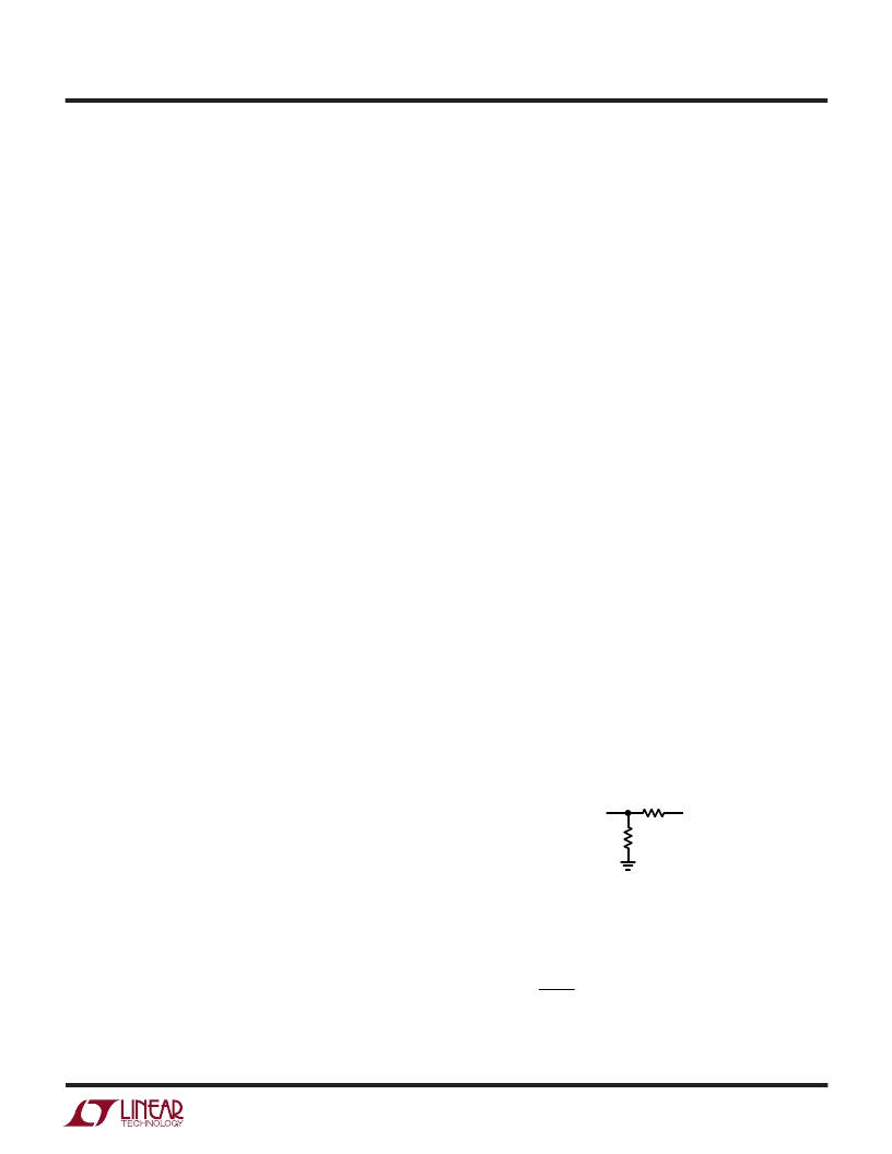
Positive Output Voltage Setting
Sensing of a positive output voltage is usually done using
a resistor divider from the output to the FB pin. The
positive input to the error amp is connected internally to a
1.25V bandgap reference. The FB pin will regulate to this
voltage.
Referring to Figure 2, R1 is determined by:
R
R
V
OUT
1 25
1
2
1
=
The FB bias current represents a small error and can
usually be ignored for values of R1
||
R2 up to 10k.
Figure 2
FB PIN
1534 F01
V
OUT
R2
R1
相关PDF资料 |
PDF描述 |
|---|---|
| LT1534CS | RADIATION HARDENED HIGH EFFICIENCY, 5 AMP SWITCHING REGULATORS |
| LT1534I | RADIATION HARDENED HIGH EFFICIENCY, 5 AMP SWITCHING REGULATORS |
| LT1534IS | RADIATION HARDENED HIGH EFFICIENCY, 5 AMP SWITCHING REGULATORS |
| LT1537C | Advanced Low Power 5V RS232 Transceiver with Small Capacitors |
| LT1537CSW | CAP ELECT 4.7UF 35V VS SMD |
相关代理商/技术参数 |
参数描述 |
|---|---|
| LT1534CS | 功能描述:IC REG BOOST ADJ 2A 16SOIC RoHS:否 类别:集成电路 (IC) >> PMIC - 稳压器 - DC DC 开关稳压器 系列:- 标准包装:2,500 系列:- 类型:降压(降压) 输出类型:固定 输出数:1 输出电压:1.2V,1.5V,1.8V,2.5V 输入电压:2.7 V ~ 20 V PWM 型:- 频率 - 开关:- 电流 - 输出:50mA 同步整流器:是 工作温度:-40°C ~ 125°C 安装类型:表面贴装 封装/外壳:10-TFSOP,10-MSOP(0.118",3.00mm 宽)裸露焊盘 包装:带卷 (TR) 供应商设备封装:10-MSOP 裸露焊盘 |
| LT1534CS#PBF | 功能描述:IC REG BOOST ADJ 2A 16SOIC RoHS:是 类别:集成电路 (IC) >> PMIC - 稳压器 - DC DC 开关稳压器 系列:- 标准包装:2,500 系列:- 类型:降压(降压) 输出类型:固定 输出数:1 输出电压:1.2V,1.5V,1.8V,2.5V 输入电压:2.7 V ~ 20 V PWM 型:- 频率 - 开关:- 电流 - 输出:50mA 同步整流器:是 工作温度:-40°C ~ 125°C 安装类型:表面贴装 封装/外壳:10-TFSOP,10-MSOP(0.118",3.00mm 宽)裸露焊盘 包装:带卷 (TR) 供应商设备封装:10-MSOP 裸露焊盘 |
| LT1534CS#TR | 功能描述:IC REG BOOST ADJ 2A 16SOIC RoHS:否 类别:集成电路 (IC) >> PMIC - 稳压器 - DC DC 开关稳压器 系列:- 设计资源:Design Support Tool 标准包装:1 系列:- 类型:升压(升压) 输出类型:固定 输出数:1 输出电压:3V 输入电压:0.75 V ~ 2 V PWM 型:- 频率 - 开关:- 电流 - 输出:100mA 同步整流器:是 工作温度:-40°C ~ 85°C 安装类型:表面贴装 封装/外壳:SOT-23-5 细型,TSOT-23-5 包装:剪切带 (CT) 供应商设备封装:TSOT-23-5 其它名称:AS1323-BTTT-30CT |
| LT1534CS#TRPBF | 功能描述:IC REG BOOST ADJ 2A 16SOIC RoHS:是 类别:集成电路 (IC) >> PMIC - 稳压器 - DC DC 开关稳压器 系列:- 设计资源:Design Support Tool 标准包装:1 系列:- 类型:升压(升压) 输出类型:固定 输出数:1 输出电压:3V 输入电压:0.75 V ~ 2 V PWM 型:- 频率 - 开关:- 电流 - 输出:100mA 同步整流器:是 工作温度:-40°C ~ 85°C 安装类型:表面贴装 封装/外壳:SOT-23-5 细型,TSOT-23-5 包装:剪切带 (CT) 供应商设备封装:TSOT-23-5 其它名称:AS1323-BTTT-30CT |
| LT1534CS-1 | 功能描述:IC REG BOOST ADJ 2A 16SOIC RoHS:否 类别:集成电路 (IC) >> PMIC - 稳压器 - DC DC 开关稳压器 系列:- 标准包装:2,500 系列:- 类型:降压(降压) 输出类型:固定 输出数:1 输出电压:1.2V,1.5V,1.8V,2.5V 输入电压:2.7 V ~ 20 V PWM 型:- 频率 - 开关:- 电流 - 输出:50mA 同步整流器:是 工作温度:-40°C ~ 125°C 安装类型:表面贴装 封装/外壳:10-TFSOP,10-MSOP(0.118",3.00mm 宽)裸露焊盘 包装:带卷 (TR) 供应商设备封装:10-MSOP 裸露焊盘 |
发布紧急采购,3分钟左右您将得到回复。