- 您现在的位置:买卖IC网 > PDF目录377707 > LT1571-2 (Linear Technology Corporation) Constant-Current/ Constant-Voltage Battery Charger with Preset Voltage and Termination Flag PDF资料下载
参数资料
| 型号: | LT1571-2 |
| 厂商: | Linear Technology Corporation |
| 英文描述: | Constant-Current/ Constant-Voltage Battery Charger with Preset Voltage and Termination Flag |
| 中文描述: | 恒流/恒压电池充电器预置电压和终止旗 |
| 文件页数: | 13/16页 |
| 文件大小: | 201K |
| 代理商: | LT1571-2 |
13
LT1571 Series
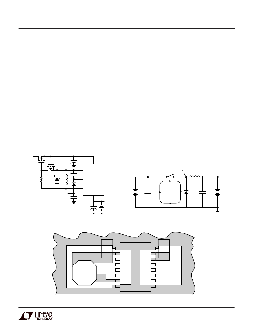
Figure 13. Critical Electrical and Thermal Path Layer for LT1571-5
Lower Dropout Voltage
For even lower dropout and/or reducing heat on the
board, the input diode D3 can be replaced with a FET (see
Figure 11). Connect a P-channel FET in place of the input
diode with its gate connected to the battery (SENSE pin)
causing the FET to turn off when the input voltage goes
low. The problem is that the gate must be pumped low so
that the FET is fully turned on even when the input is only
a volt or two above the battery voltage. Also there is a turn-
off speed issue. The FET should turn off instantly when the
input is dead shorted to avoid large current surges from
the battery back through the charger into the FET. Gate
capacitance slows turn off, so a small P-FET (Q2) dis-
charges the gate capacitance quickly in the event of an
input short. The body diode of Q2 creates the necessary
pumping action to keep the gate of Q1 low during normal
operation.
Figure 12. High Speed Switching Path
Layout Considerations
Switch rise and fall times are under 10ns for maximum
efficiency. To minimize radiation, the catch diode, SW pin
and input bypass capacitor leads should be kept as short
as possible. A ground plane should be used under the
switching circuitry to prevent interplane coupling and to
act as a thermal spreading path. All ground pins should be
connected to expand traces for low thermal resistance.
The fast-switching high current ground path including the
switch, catch diode and input capacitor should be kept
very short. Catch diode and input capacitor should be
close to the chip and terminated to the same point. This
path contains nanosecond rise and fall times with several
amps of current. The other paths contain only DC and /or
200kHz or 500kHz triwave and are less critical. Figure 12
indicates the high speed, high current switching path.
Figure 13 shows critical path layout.
Figure 11. Replacing the Input Diode
V
X
3V TO 6V
HIGH DUTY CYCLE
CONNECTION
V
IN
1571 F11
C3
L1
D2
D1
Q2
Q1
R
X
50k
Q1: Si4435DY
Q2: TP0610L
C
X
10
μ
F
V
BAT
BOOST
SW
SENSE
V
CC
LT1571
BAT
+
+
APPLICATIOU
W
U
U
1571 F12
V
BAT
L1
V
IN
HIGH
FREQUENCY
CIRCULATING
PATH
BAT
SWITCH NODE
C
IN
C
OUT
D1
L1
C
IN
GND
1571 F13
LT1571-5
GND
V
CC2
V
CC1
CAP
PROG
V
C
BAT
GND
GND
SW
BOOST
BAT2
FLAG
SELECT
SENSE
GND
相关PDF资料 |
PDF描述 |
|---|---|
| LT1571 | Octal Bus Transceivers 20-SOIC 0 to 70 |
| LT1572CS | 100kHz, 1.25A Switching Regulator with Catch Diode |
| LT1572 | 100kHz, 1.25A Switching Regulator with Catch Diode(100kHz, 1.25A 开关稳压器(带箝位二极管)) |
| LT1573C | Low Dropout PNP Regulator Driver |
| LT1573CS8 | Low Dropout PNP Regulator Driver |
相关代理商/技术参数 |
参数描述 |
|---|---|
| LT1571-5 | 制造商:LINER 制造商全称:Linear Technology 功能描述:Constant-Current/ Constant-Voltage Battery Charger with Preset Voltage and Termination Flag |
| LT-1571-511-012 | 制造商:Carling Technologies 功能描述:LT-SERIES TOGGLE SWITCH - Bulk |
| LT-1571-514-012 | 制造商:Carling Technologies 功能描述:LT-SERIES TOGGLE SWITCH - Bulk |
| LT-1571-531-012 | 制造商:Carling Technologies 功能描述:LT-SERIES TOGGLE SWITCH - Bulk |
| LT-1571-533-012 | 制造商:Carling Technologies 功能描述:LT-SERIES TOGGLE SWITCH - Bulk |
发布紧急采购,3分钟左右您将得到回复。