- 您现在的位置:买卖IC网 > PDF目录44982 > LT1702-7DB1 (POWER-ONE INC) 1-OUTPUT 550 W AC-DC REG PWR SUPPLY MODULE PDF资料下载
参数资料
| 型号: | LT1702-7DB1 |
| 厂商: | POWER-ONE INC |
| 元件分类: | 电源模块 |
| 英文描述: | 1-OUTPUT 550 W AC-DC REG PWR SUPPLY MODULE |
| 封装: | CASE T01, MODULE |
| 文件页数: | 11/33页 |
| 文件大小: | 838K |
| 代理商: | LT1702-7DB1 |
第1页第2页第3页第4页第5页第6页第7页第8页第9页第10页当前第11页第12页第13页第14页第15页第16页第17页第18页第19页第20页第21页第22页第23页第24页第25页第26页第27页第28页第29页第30页第31页第32页第33页
Rugged Environment
AC-DC Converters >100 Watt
T Series
Edition 4/4.99
19/33
MELCHER
The Power Partners.
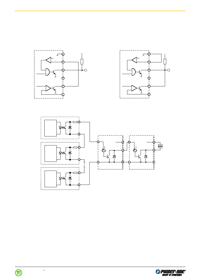
Connection in Series of Power Down and System
Good (Examples)
To achieve a logic OR function of the system good and
power down signal connect the D output to Sys In. The de-
sired function is then obtained from the system good out-
put. The output signal becomes high if the output voltage is
lower than the threshold of the power down circuit, inhibit is
applied or an internal error has occurred.
Internal
signals
20/22
Vo–
24
Sys In
26
Sys Out
Vo+
28
Inhibit
30
D
32
D set
Vo+
R
T 1000
06061
Fig. 35
System Good and Power Down connected in series.
Note: Output signal will indicate error at start-up.
Vo+
Sys Out
Vo–
T 1000
Sys In
Vo–
Vo+
Sys Out
Vo–
T 1000
Vo–
Overall
System
Good
Output
Control
Circuit
1 k
20 V
Output
Control
Circuit
1 k
20 V
Output
Control
Circuit
1 k
20 V
06059
CQ1
CQ2
CQn
22
24
12
26
24
26
12
Sys In
Fig. 36
Wired AND of electrically isolated open collector signals
(e.g. the OUT OK signal of CQ units) with the system
good signals of T units in series to achieve one signal
about the status of the whole system
Paralleling of Power Down and System Good
(Example)
To achieve a logic AND function of the System Good and
Power Down connect the D output with the system good
output. This combination generates an output signal only in
case of severe system errors. Only a T system fault to-
gether with a simultaneous Power Down of the output volt-
age will cause this output signal to become high imped-
ance.
Internal
signals
20/22
Vo–
24
Sys In
26
Sys Out
Vo+
28
Inhibit
30
D
32
D set
Vo+
R
T 1000
06062
Fig. 37
System Good and Power Down connected in parallel.
相关PDF资料 |
PDF描述 |
|---|---|
| LT1740-7ZGB1 | 1-OUTPUT AC-DC REG PWR SUPPLY MODULE |
| LT1730-7P | 1-OUTPUT AC-DC REG PWR SUPPLY MODULE |
| LT1730-7PG | 1-OUTPUT AC-DC REG PWR SUPPLY MODULE |
| LT1730-7ZGB1 | 1-OUTPUT AC-DC REG PWR SUPPLY MODULE |
| LT1740-7PDG | 1-OUTPUT AC-DC REG PWR SUPPLY MODULE |
相关代理商/技术参数 |
参数描述 |
|---|---|
| LT170A | 制造商:未知厂家 制造商全称:未知厂家 功能描述:Linear Hall-Effect Sensor |
| LT170E2 | 制造商:未知厂家 制造商全称:未知厂家 功能描述:LT170E2 |Data Sheet |
| LT170Z | 制造商:SEOUL 制造商全称:Seoul Semiconductor 功能描述:GREEN OVAL LAMP LED |
| LT171 | 制造商:SEOUL 制造商全称:Seoul Semiconductor 功能描述:RED LAMP LED |
| LT1711 | 制造商:未知厂家 制造商全称:未知厂家 功能描述:UNDERSTANDING THE SUBJECT IS CUSTOMER SERVICE |
发布紧急采购,3分钟左右您将得到回复。