- 您现在的位置:买卖IC网 > PDF目录44979 > LT1740-7Z (POWER-ONE INC) 1-OUTPUT 500 W AC-DC REG PWR SUPPLY MODULE PDF资料下载
参数资料
| 型号: | LT1740-7Z |
| 厂商: | POWER-ONE INC |
| 元件分类: | 电源模块 |
| 英文描述: | 1-OUTPUT 500 W AC-DC REG PWR SUPPLY MODULE |
| 文件页数: | 3/32页 |
| 文件大小: | 1000K |
| 代理商: | LT1740-7Z |
第1页第2页当前第3页第4页第5页第6页第7页第8页第9页第10页第11页第12页第13页第14页第15页第16页第17页第18页第19页第20页第21页第22页第23页第24页第25页第26页第27页第28页第29页第30页第31页第32页
BCD20023 Rev. AA, 3-Sep-2008
Page 11 of 32
www.power-one.com
T Series Data Sheet
500 Watt AC-DC Converters
Control Features of the Battery Chargers
According to the recommendations of battery manufacturers,
the float-charge voltage of lead-acid batteries should be
temperature-compensated. Depending on the battery type and
size, charging with different temperature coefficients may be
required. An excessive float-charge voltage may damage the
battery through overcharging.
Most
lead-acid
battery
manufacturers
recommend
cell
voltages between 2.23 V and 2.32 V, with the nominal cell
voltage defined at 20 °C and temperature coefficients per cell
between –3 and –4 mV/K.
The value of the negative temperature coefficient is specified
by the type of T temperature sensor.
With the cell voltage selector switch Z, the required cell voltage
can be adjusted at the rear of the converter, making the system
flexible to different float-charge voltages. If the selector switch
Z is not applicable, a cell voltage adjustment can also be
provided by the temperature sensor; see Temperature Sensor
T).
Although it is not recommended, the output voltage can be set
to a fixed value without temperature compensation by an
external voltage source or a resistive voltage divider at the
remote control input, for instance if the battery temperature
shall be controlled by other systems; see External Output
Voltage Control.
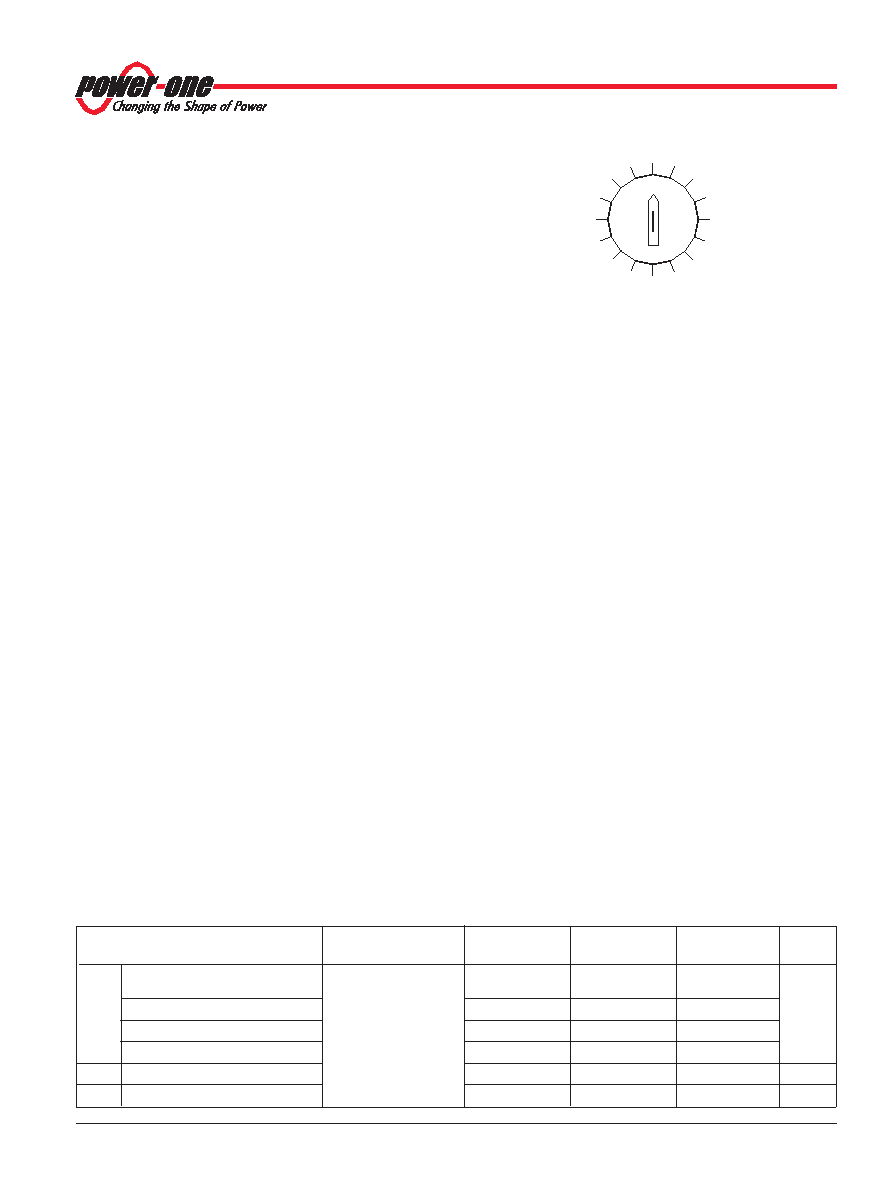
Cell Voltage Selector Switch Z
The battery chargers are equipped with the cell voltage
selector switch at the rear side, which provides an easy way of
external adjustment to the required float-charge voltage. Each
switch position allows a step in the output voltage of 10 mV per
cell, whereby the switch position "0" represents a cell voltage
of 2.23 V at 20 °C; position "C" gives 2.35 V per cell.
The cell voltage selector switch fits together with the 2.23 V
temperature sensor. The float-charge voltage is set by the
switch, and the temperature coefficient is specified by the
sensor type.
Caution: Setting the switch to the correct battery cell voltage is
vital for the proper operation of a battery system.
Note: Switching to a different cell voltage while the battery charger
is operating may cause a short distortion of the output voltage.
Potentiometer for Fine Tuning
The
battery
chargers
are
equipped
with
a
one-turn
potentiometer for fine tuning of the output voltage to within
±3.70/00 of Vo. The potentiometer is protected by a plastic
cover. To adjust the output voltage for improved current
sharing or compensation for voltage drops over the load lines,
each battery charger in a system should be unplugged and
adjusted individually to the same output voltage at equal load;
otherwise current sharing may adversely be affected.
External Output Voltage Control
The i/Vcr control input (pin 28) provides two functions:
– External adjustment of the output voltage
– Inhibiting of the converter.
A voltage <0.4 V inhibits the output, a voltage >2.5 V enables it.
With the i/Vcr input in the range of 5.5 V to 11.5 V, the output
voltage Vo set can be adjusted within a range of +3.6% to
–7.9%. This feature is optimized to control the float-charge of a
lead acid batteriy.
Outside of the control range, the sensor monitoring circuit
generates a system error signal (see also System Good).
In the case of a excessively high control voltage, the output
voltage is reduced.
The remote control input is protected against DC overvoltage
up to 60 V.
Note: An open inhibit/Vcr remote control input leads to a sensor
error signal which is indicated by the Error LED at the front and
high impedance of the "System good" signal. The output voltage is
reduced to Vcr fail condition.
2.23 V
2.24 V
2.25 V
2.26 V
2.27 V
2.28 V
2.29 V
2.30 V
2.31 V
2.32 V
2.35 V
0
4
8
C
06068
Fig. 15
Cell voltage selector switch
Table 8: Characteristics of the remote control
Characteristics
Conditions
LT/UT1240
LT1840
LT/UT1740
Unit
typ
Vo
Output voltage at:
Voltage selector switch
25.25
37.85
50.5
V
Vcr fail 2.5 – 5.5 V
Z set at 2.23 V/cell or
Vcr control 5.5 – 11.5 V
without selector switch Z
22.5 + Vcr 0.5
45 + Vcr
Vcr clamp 11.5 – 14 V
selector switch Z
28.25
42.37
56.5
Vcr fail 14 – 60 V
Vi nom, 0.5 Io nom
25.25
37.85
50.5
Rcr
Input impedance
1
M
f cr
Frequency limit
1
Hz
相关PDF资料 |
PDF描述 |
|---|---|
| LT1241MJ8 | 1 A SWITCHING CONTROLLER, 500 kHz SWITCHING FREQ-MAX, CDIP8 |
| LT1245MJ8 | 1 A SWITCHING CONTROLLER, 500 kHz SWITCHING FREQ-MAX, CDIP8 |
| LT1241CJ8 | 1 A SWITCHING CONTROLLER, 500 kHz SWITCHING FREQ-MAX, CDIP8 |
| LT1242CJ8 | 1 A SWITCHING CONTROLLER, 500 kHz SWITCHING FREQ-MAX, CDIP8 |
| LT1241IN8#TRPBF | SWITCHING CONTROLLER, 500 kHz SWITCHING FREQ-MAX, PDIP8 |
相关代理商/技术参数 |
参数描述 |
|---|---|
| LT1743 | 制造商:未知厂家 制造商全称:未知厂家 功能描述:Optoelectronic |
| LT1750 | 制造商:Pulse 功能描述:LAN,E/C,2000V - Bulk |
| LT1754ET | 制造商:Linear Technology 功能描述: |
| LT1761 | 制造商:LINER 制造商全称:Linear Technology 功能描述:45V VIN, Micropower, Low Noise, 100mA Low Dropout, Linear Regulator |
| LT1761_1 | 制造商:LINER 制造商全称:Linear Technology 功能描述:100mA, Low Noise,LDO Micropower Regulators in SOT-23 |
发布紧急采购,3分钟左右您将得到回复。