- 您现在的位置:买卖IC网 > PDF目录14074 > LT1777CS#TR (Linear Technology)IC REG BUCK ADJ 0.7A 16SOIC PDF资料下载
参数资料
| 型号: | LT1777CS#TR |
| 厂商: | Linear Technology |
| 文件页数: | 13/24页 |
| 文件大小: | 0K |
| 描述: | IC REG BUCK ADJ 0.7A 16SOIC |
| 标准包装: | 2,500 |
| 类型: | 降压(降压) |
| 输出类型: | 可调式 |
| 输出数: | 1 |
| 输出电压: | 1.24 V ~ 30 V |
| 输入电压: | 12 V ~ 48 V |
| PWM 型: | 电流模式 |
| 频率 - 开关: | 100kHz |
| 电流 - 输出: | 700mA |
| 同步整流器: | 无 |
| 工作温度: | 0°C ~ 125°C |
| 安装类型: | 表面贴装 |
| 封装/外壳: | 16-SOIC(0.154",3.90mm 宽) |
| 包装: | 带卷 (TR) |
| 供应商设备封装: | 16-SOIC |
�� �
�
�LT1777�
�APPLICATIO� N� S� I� N� FOR� M� ATIO� N�
�through� the� main� inductor� has� most� of� its� energy� concen-�
�trated� in� the� fundamental� and� lower� harmonics.)� Toroidal�
�style� inductors,� many� available� in� surface� mount� configu-�
�ration,� offer� a� reduced� external� magnetic� field,� generally� at�
�an� increase� in� cost� and� physical� size.� Although� custom�
�design� is� always� a� possibility,� most� potential� LT1777� ap-�
�plications� can� be� handled� by� the� array� of� standard,� off-the-�
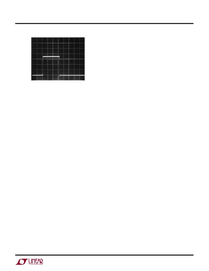
�GND�
�shelf� inductor� products� offered� by� the� major� suppliers.�
�500ns/DIV�
�1777� F06�
�Selecting� Bypass� Capacitors�
�Figure� 6.� LT1676� V� SW� Node� Voltage� Behavior�
�for� Comparison� Purposes� Only,� V� IN� =� 36V�
�Selecting� Main� Inductor�
�There� are� several� parameters� to� consider� when� selecting�
�a� main� inductor.� These� include� inductance� value,� peak�
�current� rating� (to� avoid� core� saturation),� DC� resistance,�
�construction� type,� physical� size,� and� of� course,� cost.�
�Once� the� inductance� value� is� decided,� inductor� peak�
�current� rating� and� resistance� need� to� be� considered.� Here,�
�the� inductor� peak� current� rating� refers� to� the� onset� of�
�saturation� in� the� core� material,� although� manufacturers�
�sometimes� specify� a� “peak� current� rating”� which� is� de-�
�rived� from� a� worst-case� combination� of� core� saturation�
�and� self-heating� effects.� Inductor� winding� resistance� alone�
�limits� the� inductor’s� current� carrying� capability� as� the� I� 2� R�
�power� threatens� to� overheat� the� inductor.� Remember� to�
�include� the� condition� of� output� short� circuit,� if� applicable.�
�Although� the� peak� current� rating� of� the� inductor� can� be�
�exceeded� in� short-circuit� operation,� as� core� saturation� per�
�se� is� not� destructive� to� the� core,� excess� resistive� self-�
�heating� is� still� a� potential� problem.�
�The� final� inductor� selection� is� generally� based� on� cost,�
�which� usually� translates� into� choosing� the� smallest� physi-�
�cal� size� part� which� meets� the� desired� inductance� value,�
�resistance� and� current� carrying� capability.� An� additional�
�factor� to� consider� is� that� of� physical� construction.� Briefly�
�stated,� “open”� inductors� built� on� a� rod-� or� barrel-shaped�
�core� generally� offer� the� smallest� physical� size� and� lowest�
�cost.� However� their� open� construction� does� not� contain�
�the� resulting� magnetic� field,� and� they� may� not� be� accept-�
�able� in� RFI-sensitive� applications.� (A� mitigating� factor� is�
�that,� as� mentioned� previously,� the� AC� current� passing�
�The� basic� topology� as� shown� in� the� Typical� Application� on�
�the� first� page� uses� two� bypass� capacitors,� one� for� the� V� IN�
�input� supply� and� one� for� the� V� OUT� output� supply.�
�User� selection� of� an� appropriate� output� capacitor� is� rela-�
�tively� easy,� as� this� capacitor� sees� only� the� AC� ripple� current�
�in� the� inductor� L1.� As� the� LT1777� is� designed� for� buck� or�
�step-down� applications,� output� voltage� will� nearly� always�
�be� compatible� with� tantalum� type� capacitors,� which� are�
�generally� available� in� ratings� up� to� 35V� or� so.� These�
�tantalum� types� offer� good� volumetric� efficiency,� and� many�
�are� available� with� specified� ESR� performance.� The� product�
�of� inductor� AC� ripple� current� and� output� capacitor� ESR� will�
�manifest� itself� as� peak-to-peak� voltage� ripple� on� the� output�
�node.� (Note:� If� this� ripple� becomes� too� large,� heavier�
�control� loop� compensation,� at� least� at� the� switching� fre-�
�quency,� may� be� required� on� the� V� C� pin.)�
�The� input� bypass� capacitor� can� present� a� more� difficult�
�choice.� In� a� typical� application� e.g.,� 24V� IN� to� 5V� OUT� ,�
�relatively� heavy� V� IN� current� is� drawn� by� the� power� switch�
�for� only� a� small� portion� of� the� oscillator� period� (low� ON�
�duty� cycle).� The� resulting� RMS� ripple� current,� for� which�
�the� capacitor� must� be� rated,� can� be� several� times� the� DC�
�average� V� IN� current.� The� straightforward� choice� for� a� low�
�volume,� surface� mountable� electrolytic� capacitor� with�
�good� ESR/ripple� current� ratings� is� a� tantalum� type.� How-�
�ever,� worst-case� (high)� input� voltage� coupled� with� stan-�
�dard� capacitor� voltage� derating� may� exceed� the� 35V� or� so�
�for� which� tantalum� capacitors� are� generally� available.�
�Relatively� bulky� “high� frequency”� aluminum� electrolytic�
�types,� specifically� constructed� and� rated� for� switching�
�supply� applications,� may� then� be� the� only� choice.�
�Additionally,� it� may� be� advantageous� to� parallel� the� input�
�and� output� capacitors� with� 0.1� μ� F� ceramic� bypass� capaci-�
�13�
�相关PDF资料 |
PDF描述 |
|---|---|
| HM71-40101LFTR | HIGH PERF LOW COST INDUCTORS |
| HM71-40680LFTR | HIGH PERF LOW COST INDUCTORS |
| LTC1046IN8#PBF | IC REG SWITCHED CAP DIV INV 8DIP |
| HM71-40470LFTR | HIGH PERF LOW COST INDUCTORS |
| LTC1046IN8 | IC REG SWITCHED CAP DIV INV 8DIP |
相关代理商/技术参数 |
参数描述 |
|---|---|
| LT1777I | 制造商:LINER 制造商全称:Linear Technology 功能描述:Low Noise Step-Down Switching Regulator |
| LT1777IS | 功能描述:IC REG BUCK ADJ 0.7A 16SOIC RoHS:否 类别:集成电路 (IC) >> PMIC - 稳压器 - DC DC 开关稳压器 系列:- 标准包装:2,500 系列:- 类型:降压(降压) 输出类型:固定 输出数:1 输出电压:1.2V,1.5V,1.8V,2.5V 输入电压:2.7 V ~ 20 V PWM 型:- 频率 - 开关:- 电流 - 输出:50mA 同步整流器:是 工作温度:-40°C ~ 125°C 安装类型:表面贴装 封装/外壳:10-TFSOP,10-MSOP(0.118",3.00mm 宽)裸露焊盘 包装:带卷 (TR) 供应商设备封装:10-MSOP 裸露焊盘 |
| LT1777IS#PBF | 功能描述:IC REG BUCK ADJ 0.7A 16SOIC RoHS:是 类别:集成电路 (IC) >> PMIC - 稳压器 - DC DC 开关稳压器 系列:- 标准包装:2,500 系列:- 类型:降压(降压) 输出类型:固定 输出数:1 输出电压:1.2V,1.5V,1.8V,2.5V 输入电压:2.7 V ~ 20 V PWM 型:- 频率 - 开关:- 电流 - 输出:50mA 同步整流器:是 工作温度:-40°C ~ 125°C 安装类型:表面贴装 封装/外壳:10-TFSOP,10-MSOP(0.118",3.00mm 宽)裸露焊盘 包装:带卷 (TR) 供应商设备封装:10-MSOP 裸露焊盘 |
| LT1777IS#PBF | 制造商:Linear Technology 功能描述:DC/DC Converter IC |
| LT1777IS#TR | 功能描述:IC REG BUCK ADJ 0.7A 16SOIC RoHS:否 类别:集成电路 (IC) >> PMIC - 稳压器 - DC DC 开关稳压器 系列:- 标准包装:2,500 系列:- 类型:降压(降压) 输出类型:固定 输出数:1 输出电压:1.2V,1.5V,1.8V,2.5V 输入电压:2.7 V ~ 20 V PWM 型:- 频率 - 开关:- 电流 - 输出:50mA 同步整流器:是 工作温度:-40°C ~ 125°C 安装类型:表面贴装 封装/外壳:10-TFSOP,10-MSOP(0.118",3.00mm 宽)裸露焊盘 包装:带卷 (TR) 供应商设备封装:10-MSOP 裸露焊盘 |
发布紧急采购,3分钟左右您将得到回复。