- 您现在的位置:买卖IC网 > PDF目录44982 > LT1871EMS-7#PBF (LINEAR TECHNOLOGY CORP) SWITCHING CONTROLLER, 1000 kHz SWITCHING FREQ-MAX, PDSO10 PDF资料下载
参数资料
| 型号: | LT1871EMS-7#PBF |
| 厂商: | LINEAR TECHNOLOGY CORP |
| 元件分类: | 稳压器 |
| 英文描述: | SWITCHING CONTROLLER, 1000 kHz SWITCHING FREQ-MAX, PDSO10 |
| 封装: | LEAD FREE, PLASTIC, MSOP-10 |
| 文件页数: | 9/32页 |
| 文件大小: | 461K |
| 代理商: | LT1871EMS-7#PBF |
第1页第2页第3页第4页第5页第6页第7页第8页当前第9页第10页第11页第12页第13页第14页第15页第16页第17页第18页第19页第20页第21页第22页第23页第24页第25页第26页第27页第28页第29页第30页第31页第32页
LTC1871-7
17
18717fc
APPLICATIONS INFORMATION
For some designs it may be possible to choose a single
capacitor type that satises both the ESR and bulk C require-
ments for the design. In certain demanding applications,
however, the ripple voltage can be improved signicantly
by connecting two or more types of capacitors in paral-
lel. For example, using a low ESR ceramic capacitor can
minimize the ESR step, while an electrolytic capacitor can
be used to supply the required bulk C.
Once the output capacitor ESR and bulk capacitance have
been determined, the overall ripple voltage waveform
should be veried on a dedicated PC board (see Board
Layout section for more information on component place-
ment). Lab breadboards generally suffer from excessive
series inductance (due to inter-component wiring), and
these parasitics can make the switching waveforms look
signicantly worse than they would be on a properly
designed PC board.
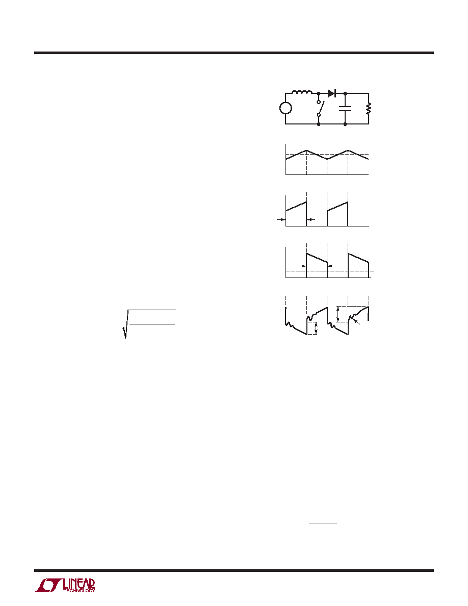
The output capacitor in a boost regulator experiences high
RMS ripple currents, as shown in Figure 13. The RMS
output capacitor ripple current is:
IRMS(COUT) IO(MAX)
VO –VIN(MIN)
VIN(MIN)
Note that the ripple current ratings from capacitor manu-
facturers are often based on only 2000 hours of life. This
makes it advisable to further derate the capacitor or to
choose a capacitor rated at a higher temperature than
required. Several capacitors may also be placed in parallel
to meet size or height requirements in the design.
In surface mount applications, multiple capacitors may
have to be placed in parallel in order to meet the ESR or
RMS current handling requirements of the application.
Aluminum electrolytic and dry tantalum capacitors are
both available in surface mount packages. In the case of
tantalum, it is critical that the capacitors have been surge
tested for use in switching power supplies. Also, ceramic
capacitors are now available with extremely low ESR, ESL
and high ripple current ratings.
Boost Converter: Input Capacitor Selection
The input capacitor of a boost converter is less critical
than the output capacitor, due to the fact that the inductor
is in series with the input and the input current waveform
is continuous (see Figure 13b). The input voltage source
impedance determines the size of the input capacitor,
which is typically in the range of 10μF to 100μF. A low ESR
capacitor is recommended, although it is not as critical as
for the output capacitor.
The RMS input capacitor ripple current for a boost con-
verter is:
IRMS(CIN) = 0.3
VIN(MIN)
L f
DMAX
Figure 13. Switching Waveforms for a Boost Converter
VIN
LD
SW
13a. Circuit Diagram
13b. Inductor and Input Currents
COUT
VOUT
RL
IIN
IL
13c. Switch Current
ISW
tON
13d. Diode and Output Currents
13e. Output Voltage Ripple Waveform
IO
18717 F13
ID
VOUT
(AC)
tOFF
ΔVESR
RINGING DUE TO
TOTAL INDUCTANCE
(BOARD + CAP)
ΔVCOUT
相关PDF资料 |
PDF描述 |
|---|---|
| LT1871EMS-7 | SWITCHING CONTROLLER, 1000 kHz SWITCHING FREQ-MAX, PDSO10 |
| LT1871EMS-7#TR | SWITCHING CONTROLLER, 1000 kHz SWITCHING FREQ-MAX, PDSO10 |
| LT1912EMSE#PBF | 4.2 A SWITCHING REGULATOR, 240 kHz SWITCHING FREQ-MAX, PDSO10 |
| LT1932ES6#TRM | 0.78 A SWITCHING REGULATOR, 1600 kHz SWITCHING FREQ-MAX, PDSO6 |
| LT1933HDCB#TRM | 1.05 A SWITCHING REGULATOR, 600 kHz SWITCHING FREQ-MAX, PDSO6 |
相关代理商/技术参数 |
参数描述 |
|---|---|
| LT1871EMS-7-TR | 制造商:LINER 制造商全称:Linear Technology 功能描述:High Input Voltage,Current Mode Boost, Flyback and SEPIC Controller |
| LT1871EMS-7-TRPBF | 制造商:LINER 制造商全称:Linear Technology 功能描述:High Input Voltage,Current Mode Boost, Flyback and SEPIC Controller |
| LT1871IMS-7 | 制造商:LINER 制造商全称:Linear Technology 功能描述:High Input Voltage,Current Mode Boost, Flyback and SEPIC Controller |
| LT1871IMS-7-PBF | 制造商:LINER 制造商全称:Linear Technology 功能描述:High Input Voltage,Current Mode Boost, Flyback and SEPIC Controller |
| LT1871IMS-7-TR | 制造商:LINER 制造商全称:Linear Technology 功能描述:High Input Voltage,Current Mode Boost, Flyback and SEPIC Controller |
发布紧急采购,3分钟左右您将得到回复。