- 您现在的位置:买卖IC网 > PDF目录44983 > LT1871EMS-7 (LINEAR TECHNOLOGY CORP) SWITCHING CONTROLLER, 1000 kHz SWITCHING FREQ-MAX, PDSO10 PDF资料下载
参数资料
| 型号: | LT1871EMS-7 |
| 厂商: | LINEAR TECHNOLOGY CORP |
| 元件分类: | 稳压器 |
| 英文描述: | SWITCHING CONTROLLER, 1000 kHz SWITCHING FREQ-MAX, PDSO10 |
| 封装: | PLASTIC, MSOP-10 |
| 文件页数: | 13/32页 |
| 文件大小: | 461K |
| 代理商: | LT1871EMS-7 |
第1页第2页第3页第4页第5页第6页第7页第8页第9页第10页第11页第12页当前第13页第14页第15页第16页第17页第18页第19页第20页第21页第22页第23页第24页第25页第26页第27页第28页第29页第30页第31页第32页
LTC1871-7
20
18717fc
APPLICATIONS INFORMATION
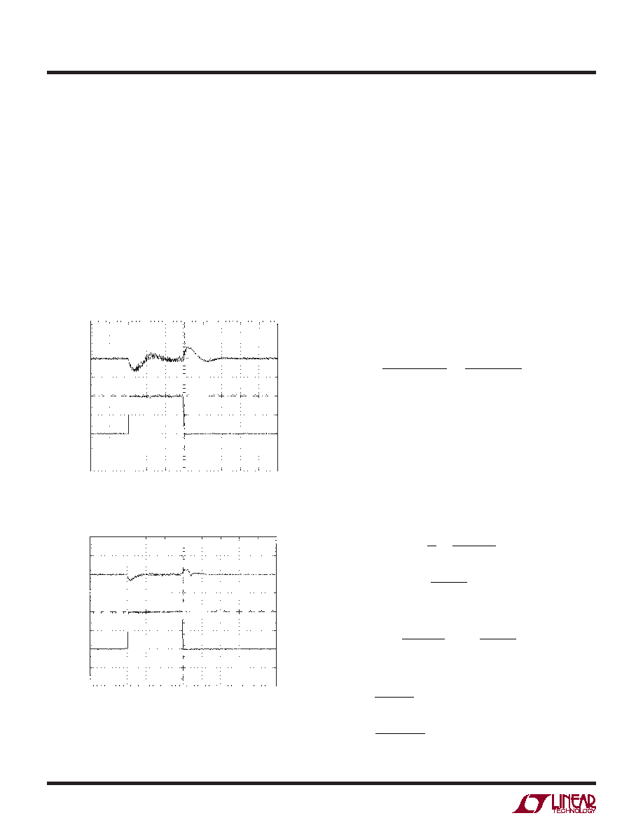
Checking Transient Response
The regulator loop response can be veried by looking at
the load transient response at minimum and maximum
VIN. Switching regulators generally take several cycles to
respond to an instantaneous step in resistive load current.
When the load step occurs, VO immediately shifts by an
amount equal to (ΔILOAD)(ESR), and then CO begins to
charge or discharge (depending on the direction of the load
step) as shown in Figure 14. The regulator feedback loop
acts on the resulting error amp output signal to return VO
to its steady-state value. During this recovery time, VO can
be monitored for overshoot or ringing that would indicate
a stability problem.
A second, more severe transient can occur when con-
necting loads with large (>1μF) supply bypass capacitors.
The discharged bypass capacitors are effectively put in
parallel with CO, causing a nearly instantaneous drop in
VO. No regulator can deliver enough current to prevent
this problem if the load switch resistance is low and it is
driven quickly. The only solution is to limit the rise time
of the switch drive in order to limit the inrush current
di/dt to the load.
Boost Converter Design Example
The design example given here will be for the circuit shown
in Figure 9. The input voltage is 8V to 28V, and the output
is 42V at a maximum load current of 1.5A.
1. The maximum duty cycle is:
D=
VO + VD –VIN
VO + VD
= 42+ 0.4 – 8
42+ 0.4
= 81.1%
2. Pulse-skip operation is chosen so the MODE/SYNC pin
is shorted to INTVCC.
3. The operating frequency is chosen to be 250kHz to
reduce the size of the inductor. From Figure 5, the
resistor from the FREQ pin to ground is 100k.
4. An inductor ripple current of 40% of the maximum load
current is chosen, so the peak input current (which is
also the minimum saturation current) is:
IIN(PEAK) = 1+ 2
IO(MAX)
1–DMAX
= 1.2 1.5
1– 0.81
= 9.47A
The inductor ripple current is:
IL =
IO(MAX)
1–DMAX
= 0.4 1.5
1– 0.81
= 3.2A
And so the inductor value is:
L =
VIN(MIN)
IL f
DMAX
=
8
3.2 250k
0.81= 8.1μH
Figure 14a. Load Transient Response for the Circuit in Figure 9
Figure 14b. Load Transient Response for the Circuit in Figure 9
VOUT
500mV/DIV
IOUT
0.5A/DIV
0.5A
250μs/DIV
18717 F14a
1.5A
VIN = 8V
VOUT
500mV/DIV
IOUT
0.5A/DIV
0.5A
250μs/DIV
18717 F14b
1.5A
VIN = 28V
相关PDF资料 |
PDF描述 |
|---|---|
| LT1871EMS-7#TR | SWITCHING CONTROLLER, 1000 kHz SWITCHING FREQ-MAX, PDSO10 |
| LT1912EMSE#PBF | 4.2 A SWITCHING REGULATOR, 240 kHz SWITCHING FREQ-MAX, PDSO10 |
| LT1932ES6#TRM | 0.78 A SWITCHING REGULATOR, 1600 kHz SWITCHING FREQ-MAX, PDSO6 |
| LT1933HDCB#TRM | 1.05 A SWITCHING REGULATOR, 600 kHz SWITCHING FREQ-MAX, PDSO6 |
| LT1933HDCB | 1.05 A SWITCHING REGULATOR, 600 kHz SWITCHING FREQ-MAX, PDSO6 |
相关代理商/技术参数 |
参数描述 |
|---|---|
| LT1871EMS-7-PBF | 制造商:LINER 制造商全称:Linear Technology 功能描述:High Input Voltage,Current Mode Boost, Flyback and SEPIC Controller |
| LT1871EMS-7-TR | 制造商:LINER 制造商全称:Linear Technology 功能描述:High Input Voltage,Current Mode Boost, Flyback and SEPIC Controller |
| LT1871EMS-7-TRPBF | 制造商:LINER 制造商全称:Linear Technology 功能描述:High Input Voltage,Current Mode Boost, Flyback and SEPIC Controller |
| LT1871IMS-7 | 制造商:LINER 制造商全称:Linear Technology 功能描述:High Input Voltage,Current Mode Boost, Flyback and SEPIC Controller |
| LT1871IMS-7-PBF | 制造商:LINER 制造商全称:Linear Technology 功能描述:High Input Voltage,Current Mode Boost, Flyback and SEPIC Controller |
发布紧急采购,3分钟左右您将得到回复。