- 您现在的位置:买卖IC网 > PDF目录44983 > LT1934IDCB-1 (LINEAR TECHNOLOGY CORP) 0.49 A SWITCHING REGULATOR, PDSO6 PDF资料下载
参数资料
| 型号: | LT1934IDCB-1 |
| 厂商: | LINEAR TECHNOLOGY CORP |
| 元件分类: | 稳压器 |
| 英文描述: | 0.49 A SWITCHING REGULATOR, PDSO6 |
| 封装: | 2 X 3 MM, 0.80 MM HEIGHT, PLASTIC, MO-229, DFN-6 |
| 文件页数: | 19/20页 |
| 文件大小: | 234K |
| 代理商: | LT1934IDCB-1 |
LT1934/LT1934-1
8
1934fe
Which One to Use: LT1934 or LT1934-1?
The only difference between the LT1934 and LT1934-1
is the peak current through the internal switch and the
inductor. If your maximum load current is less than 60mA,
use the LT1934-1. If your maximum load is higher, use
the LT1934; it can supply up to ~300mA.
While the LT1934-1 can’t deliver as much output current,
it has other advantages. The lower peak switch current
allows the use of smaller components (input capacitor,
inductor and output capacitor). The ripple current at the
input of the LT1934-1 circuit will be smaller and may be
an important consideration if the input supply is current
limited or has high impedance. The LT1934-1’s current
draw during faults (output overload or short) and start-
up is lower.
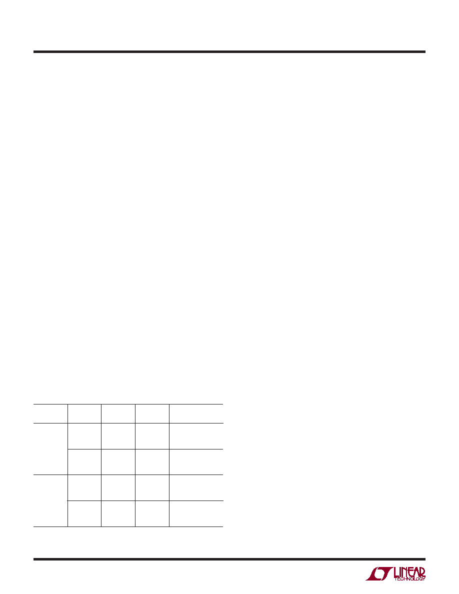
The maximum load current that the LT1934 or LT1934-1
can deliver depends on the value of the inductor used.
Table 1 lists inductor value, minimum output capacitor
and maximum load for 3.3V and 5V circuits. Increasing
the value of the capacitor will lower the output voltage
ripple. Component selection is covered in more detail in
the following sections.
Minimum Input Voltage
The minimum input voltage required to generate a par-
ticular output voltage is determined by either the LT1934’s
undervoltage lockout of ~3V or by its maximum duty cycle.
APPLICATIONS INFORMATION
The duty cycle is the fraction of time that the internal
switch is on and is determined by the input and output
voltages:
DC = (VOUT + VD)/(VIN – VSW + VD)
where VD is the forward voltage drop of the catch diode
(~0.4V) and VSW is the voltage drop of the internal switch
(~0.3V at maximum load for the LT1934, ~0.1V for the
LT1934-1). This leads to a minimum input voltage of:
VIN(MIN) = (VOUT + VD)/DCMAX – VD + VSW
with DCMAX = 0.85.
Inductor Selection
A good rst choice for the inductor value is:
L = 2.5 (VOUT + VD) 1.8μs/ILIM
where ILIM is the switch current limit (400mA for the
LT1934 and 120mA for the LT1934-1). This choice provides
a worst-case maximum load current of 250mA (60mA for
the LT1934-1). The inductor’s RMS current rating must
be greater than the load current and its saturation current
should be greater than ILIM. To keep efciency high, the
series resistance (DCR) should be less than 0.3Ω (1Ω
for the LT1934-1). Table 2 lists several vendors and types
that are suitable.
This simple rule may not provide the optimum value for
your application. If the load current is less, then you can
relax the value of the inductor and operate with higher
ripple current. This allows you to use a physically smaller
inductor, or one with a lower DCR resulting in higher
efciency. The following provides more details to guide
inductor selection. First, the value must be chosen so that
the LT1934 can supply the maximum load current drawn
from the output. Second, the inductor must be rated ap-
propriately so that the LT1934 will function reliably and
the inductor itself will not be overly stressed.
Detailed Inductor Selection and
Maximum Load Current
The square wave that the LT1934 produces at its switch
pin results in a triangle wave of current in the inductor. The
LT1934 limits the peak inductor current to ILIM. Because
Table 1
PART
VOUT
L
MINIMUM
COUT
MAXIMUM
LOAD
LT1934
3.3V
100μH
47μH
33μH
100μH
47μH
33μH
300mA
250mA
200mA
5V
150μH
68μH
47μH
33μH
22μH
300mA
250mA
200mA
LT1934-1
3.3V
150μH
100μH
68μH
15μH
10μH
60mA
45mA
20mA
5V
220μH
150μH
100μH
10μH
4.7μH
60mA
45mA
20mA
相关PDF资料 |
PDF描述 |
|---|---|
| LT1934IDCB | 0.49 A SWITCHING REGULATOR, PDSO6 |
| LT1934IS6#TR | 0.49 A SWITCHING REGULATOR, PDSO6 |
| LT1934IS6-1#PBF | 0.16 A SWITCHING REGULATOR, PDSO6 |
| LT1938IDD#PBF | 4 A SWITCHING REGULATOR, 3300 kHz SWITCHING FREQ-MAX, PDSO10 |
| LT1956-5EGN | 3 A SWITCHING REGULATOR, 570 kHz SWITCHING FREQ-MAX, PDSO16 |
相关代理商/技术参数 |
参数描述 |
|---|---|
| LT1934IDCB-1#TRMPBF | 功能描述:IC REG BUCK ADJ 60MA 6DFN RoHS:是 类别:集成电路 (IC) >> PMIC - 稳压器 - DC DC 开关稳压器 系列:- 标准包装:2,500 系列:- 类型:降压(降压) 输出类型:固定 输出数:1 输出电压:1.2V,1.5V,1.8V,2.5V 输入电压:2.7 V ~ 20 V PWM 型:- 频率 - 开关:- 电流 - 输出:50mA 同步整流器:是 工作温度:-40°C ~ 125°C 安装类型:表面贴装 封装/外壳:10-TFSOP,10-MSOP(0.118",3.00mm 宽)裸露焊盘 包装:带卷 (TR) 供应商设备封装:10-MSOP 裸露焊盘 |
| LT1934IDCB-1#TRPBF | 功能描述:IC REG BUCK ADJ 60MA 6DFN RoHS:是 类别:集成电路 (IC) >> PMIC - 稳压器 - DC DC 开关稳压器 系列:- 标准包装:2,500 系列:- 类型:降压(降压) 输出类型:固定 输出数:1 输出电压:1.2V,1.5V,1.8V,2.5V 输入电压:2.7 V ~ 20 V PWM 型:- 频率 - 开关:- 电流 - 输出:50mA 同步整流器:是 工作温度:-40°C ~ 125°C 安装类型:表面贴装 封装/外壳:10-TFSOP,10-MSOP(0.118",3.00mm 宽)裸露焊盘 包装:带卷 (TR) 供应商设备封装:10-MSOP 裸露焊盘 |
| LT1934IS6 | 制造商:LINER 制造商全称:Linear Technology 功能描述:Micropower Step-Down Switching Regulators in ThinSOT |
| LT1934IS6#PBF | 制造商:Linear Technology 功能描述:Conv DC-DC Single Step Down 3.2V to 34V 6-Pin TSOT-23 制造商:Linear Technology 功能描述:SP-SWREG/Monolithic, Cut Tape 300mA (Iout), Micropower Step-Down |
| LT1934IS6#TR | 功能描述:IC REG BUCK ADJ 0.3A SOT23-6 RoHS:否 类别:集成电路 (IC) >> PMIC - 稳压器 - DC DC 开关稳压器 系列:- 标准包装:2,500 系列:- 类型:升压(升压) 输出类型:可调式 输出数:1 输出电压:1.24 V ~ 30 V 输入电压:1.5 V ~ 12 V PWM 型:电流模式,混合 频率 - 开关:600kHz 电流 - 输出:500mA 同步整流器:无 工作温度:-40°C ~ 85°C 安装类型:表面贴装 封装/外壳:8-SOIC(0.154",3.90mm 宽) 包装:带卷 (TR) 供应商设备封装:8-SOIC |
发布紧急采购,3分钟左右您将得到回复。