- 您现在的位置:买卖IC网 > PDF目录44984 > LT3470AIDDB#PBF (LINEAR TECHNOLOGY CORP) 0.56 A SWITCHING REGULATOR, PDSO8 PDF资料下载
参数资料
| 型号: | LT3470AIDDB#PBF |
| 厂商: | LINEAR TECHNOLOGY CORP |
| 元件分类: | 稳压器 |
| 英文描述: | 0.56 A SWITCHING REGULATOR, PDSO8 |
| 封装: | 3 X 2 MM, 0.75 MM HEIGHT, LEAD FREE, PLASTIC, MO-229WECD-1, DFN-8 |
| 文件页数: | 2/20页 |
| 文件大小: | 197K |
| 代理商: | LT3470AIDDB#PBF |
LT3470A
10
3470afb
APPLICATIONS INFORMATION
Input Capacitor
Step-down regulators draw current from the input sup-
ply in pulses with very fast rise and fall times. The input
capacitor is required to reduce the resulting voltage ripple
at the VIN pin of the LT3470A and to force this switching
current into a tight local loop, minimizing EMI. The input
capacitor must have low impedance at the switching
frequency to do this effectively. A 1μF to 2.2μF ceramic
capacitor satisfies these requirements.
If the input source impedance is high, a larger value ca-
pacitor may be required to keep input ripple low. In this
case, an electrolytic of 10μF or more in parallel with a 1μF
ceramic is a good combination. Be aware that the input
capacitor is subject to large surge currents if the LT3470A
circuit is connected to a low impedance supply, and that
some electrolytic capacitors (in particular tantalum) must
be specified for such use.
Output Capacitor and Output Ripple
The output capacitor filters the inductor’s ripple current
and stores energy to satisfy the load current when the
LT3470A is quiescent. In order to keep output voltage
ripple low, the impedance of the capacitor must be low at
the LT3470A’s switching frequency. The capacitor’s equiva-
lent series resistance (ESR) determines this impedance.
Choose one with low ESR intended for use in switching
regulators. The contribution to ripple voltage due to the
ESR is approximately ILIM ESR. ESR should be less than
~150mΩ. The value of the output capacitor must be large
enough to accept the energy stored in the inductor without
a large change in output voltage. Setting this voltage step
equal to 1% of the output voltage, the output capacitor
must be:
COUT > 50 L
ILIM
VOUT
2
Where ILIM is the top current limit with VFB= 0V (see Electri-
cal Characteristics). For example, an LT3470A producing
3.3V with L = 33μH requires 22μF. The calculated value
can be relaxed if small circuit size is more important than
low output ripple.
Sanyo’s POSCAP series in B-case and provides very good
performance in a small package for the LT3470A. Similar
performance in traditional tantalum capacitors requires
a larger package (C-case). With a high quality capacitor
filtering the ripple current from the inductor, the output
voltage ripple is determined by the delay in the LT3470A’s
feedback comparator. This ripple can be reduced further
by adding a small (typically 22pF) phase lead capacitor
between the output and the feedback pin.
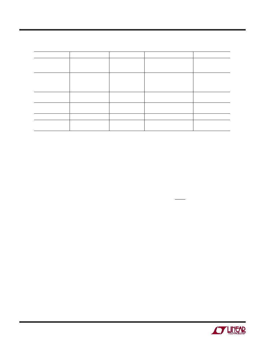
Table 2. Inductor Vendors
VENDOR
URL
PART SERIES
INDUCTANCE RANGE (μH)
SIZE (mm)
Coilcraft
www.coilcraft.com
DO1605
ME3220
DO3314
10 to 47
1.8 × 5.4 × 4.2
2.0 × 3.2 × 2.5
1.4 × 3.3 × 3.3
Sumida
www.sumida.com
CR32
CDRH3D16/HP
CDRH3D28
CDRH2D18/HP
10 to 47
10 to 33
10 to 47
10 to 15
3.0 × 3.8 × 4.1
1.8 × 4.0 × 4.0
3.0 × 4.0 × 4.0
2.0 × 3.2 × 3.2
Toko
www.tokoam.com
DB320C
D52LC
10 to 27
10 to 47
2.0 × 3.8 × 3.8
2.0 × 5.0 × 5.0
Würth Elektronik
www.we-online.com
WE-PD2 Typ S
WE-TPC Typ S
10 to 47
10 to 22
3.2 × 4.0 × 4.5
1.6 × 3.8 × 3.8
Coiltronics
www.cooperet.com
SD10
10 to 47
1.0 × 5.0 × 5.0
Murata
www.murata.com
LQH43C
LQH32C
10 to 47
10 to 15
2.6 × 3.2 × 4.5
1.6 × 2.5 × 3.2
相关PDF资料 |
PDF描述 |
|---|---|
| LT3470HDDB#TR | 0.2 A SWITCHING REGULATOR, PDSO8 |
| LT3485EDD-0#TRPBF | SPECIALTY ANALOG CIRCUIT, PDSO10 |
| LT3485EDD-0#TR | SPECIALTY ANALOG CIRCUIT, PDSO10 |
| LT3493EDCB-3#TR | 2.2 A SWITCHING REGULATOR, 815 kHz SWITCHING FREQ-MAX, PDSO6 |
| LT3494EDDB#PBF | 0.25 A SWITCHING REGULATOR, PDSO8 |
相关代理商/技术参数 |
参数描述 |
|---|---|
| LT3470AIDDB-TRPBF | 制造商:LINER 制造商全称:Linear Technology 功能描述:Micropower Buck Regulator with Integrated Boost and Catch Diodes |
| LT3470EDDB | 制造商:Linear Technology 功能描述:Conv DC-DC Single Step Down 4V to 40V 8-Pin DFN EP |
| LT3470EDDB#PBF | 制造商:Linear Technology 功能描述:BUCK 40V 0.3A 8DFN 制造商:Linear Technology 功能描述:BUCK, 40V, 0.3A, 8DFN |
| LT3470EDDB#TRMPBF | 功能描述:IC REG BUCK ADJ 0.2A 8DFN RoHS:是 类别:集成电路 (IC) >> PMIC - 稳压器 - DC DC 开关稳压器 系列:- 标准包装:2,500 系列:- 类型:升压(升压) 输出类型:可调式 输出数:1 输出电压:1.24 V ~ 30 V 输入电压:1.5 V ~ 12 V PWM 型:电流模式,混合 频率 - 开关:600kHz 电流 - 输出:500mA 同步整流器:无 工作温度:-40°C ~ 85°C 安装类型:表面贴装 封装/外壳:8-SOIC(0.154",3.90mm 宽) 包装:带卷 (TR) 供应商设备封装:8-SOIC |
| LT3470EDDB#TRPBF | 功能描述:IC REG BUCK ADJ 0.2A 8DFN RoHS:是 类别:集成电路 (IC) >> PMIC - 稳压器 - DC DC 开关稳压器 系列:- 标准包装:2,500 系列:- 类型:升压(升压) 输出类型:可调式 输出数:1 输出电压:1.24 V ~ 30 V 输入电压:1.5 V ~ 12 V PWM 型:电流模式,混合 频率 - 开关:600kHz 电流 - 输出:500mA 同步整流器:无 工作温度:-40°C ~ 85°C 安装类型:表面贴装 封装/外壳:8-SOIC(0.154",3.90mm 宽) 包装:带卷 (TR) 供应商设备封装:8-SOIC |
发布紧急采购,3分钟左右您将得到回复。