- 您现在的位置:买卖IC网 > PDF目录14813 > LT3480EDD#PBF (Linear Technology)IC REG BUCK ADJ 2A 10DFN PDF资料下载
参数资料
| 型号: | LT3480EDD#PBF |
| 厂商: | Linear Technology |
| 文件页数: | 11/24页 |
| 文件大小: | 0K |
| 描述: | IC REG BUCK ADJ 2A 10DFN |
| 标准包装: | 121 |
| 类型: | 降压(降压) |
| 输出类型: | 可调式 |
| 输出数: | 1 |
| 输出电压: | 0.79 V ~ 20 V |
| 输入电压: | 3.6 V ~ 36 V |
| PWM 型: | 电流模式,混合 |
| 频率 - 开关: | 200kHz ~ 2.4MHz |
| 电流 - 输出: | 2A |
| 同步整流器: | 无 |
| 工作温度: | -40°C ~ 85°C |
| 安装类型: | 表面贴装 |
| 封装/外壳: | 10-WFDFN 裸露焊盘 |
| 包装: | 管件 |
| 供应商设备封装: | 10-DFN(3x3) |
| 产品目录页面: | 1331 (CN2011-ZH PDF) |
�� �
�
�LT3480�
�APPLICATIONS� INFORMATION�
�where� V� D� is� the� voltage� drop� of� the� catch� diode� (~0.4V),�
�V� IN(MAX)� is� the� maximum� input� voltage,� V� OUT� is� the� output�
�voltage,� f� SW� is� the� switching� frequency� (set� by� RT),� and� L�
�is� in� the� inductor� value.�
�The� inductor’s� RMS� current� rating� must� be� greater� than� the�
�maximum� load� current� and� its� saturation� current� should� be�
�about� 30%� higher.� For� robust� operation� in� fault� conditions�
�(start-up� or� short� circuit)� and� high� input� voltage� (>30V),�
�the� saturation� current� should� be� above� 3.5A.� To� keep� the�
�efficiency� high,� the� series� resistance� (DCR)� should� be� less�
�than� 0.1� ,� and� the� core� material� should� be� intended� for�
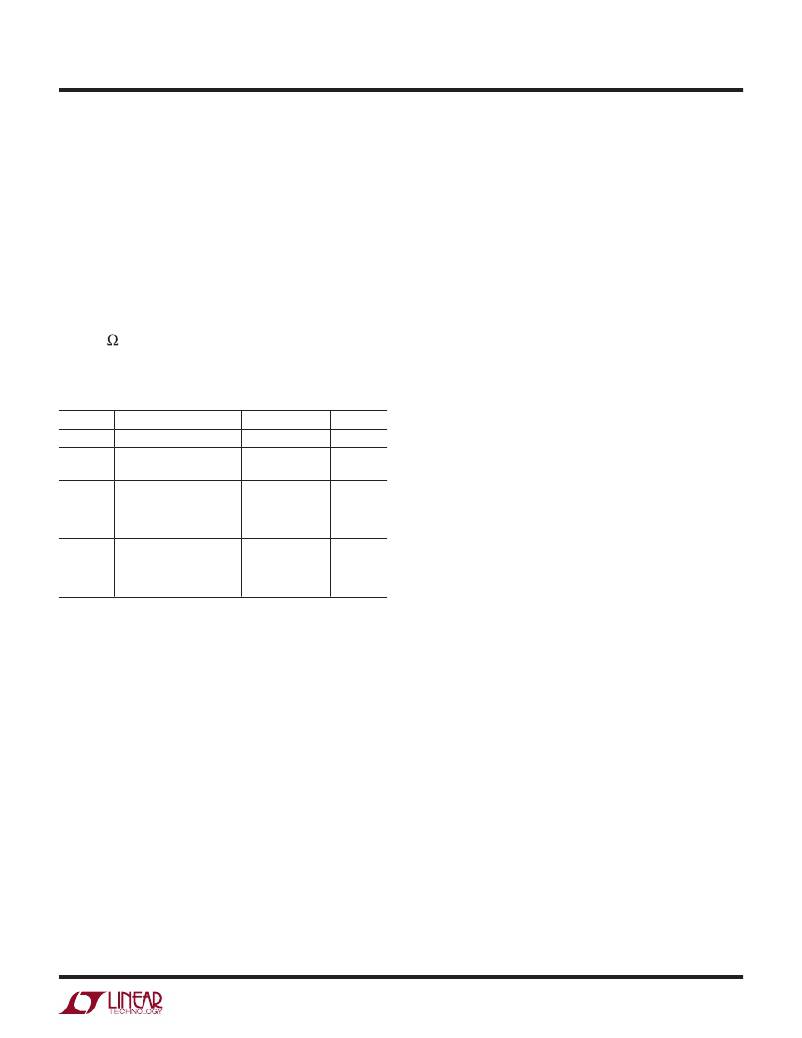
�high� frequency� applications.� Table� 1� lists� several� vendors�
�and� suitable� types.�
�Table� 1.� Inductor� Vendors�
�VENDOR� URL� PART� SERIES� TYPE�
�Murata� www.murata.com� LQH55D� Open�
�TDK� www.componenttdk.com� SLF7045� Shielded�
�SLF10145� Shielded�
�Toko� www.toko.com� D62CB� Shielded�
�D63CB� Shielded�
�D75C� Shielded�
�D75F� Open�
�Sumida� www.sumida.com� CR54� Open�
�CDRH74� Shielded�
�CDRH6D38� Shielded�
�CR75� Open�
�Of� course,� such� a� simple� design� guide� will� not� always� re-�
�sult� in� the� optimum� inductor� for� your� application.� A� larger�
�value� inductor� provides� a� slightly� higher� maximum� load�
�current� and� will� reduce� the� output� voltage� ripple.� If� your�
�load� is� lower� than� 2A,� then� you� can� decrease� the� value� of�
�the� inductor� and� operate� with� higher� ripple� current.� This�
�allows� you� to� use� a� physically� smaller� inductor,� or� one�
�with� a� lower� DCR� resulting� in� higher� efficiency.� There� are�
�several� graphs� in� the� Typical� Performance� Characteristics�
�section� of� this� data� sheet� that� show� the� maximum� load�
�current� as� a� function� of� input� voltage� and� inductor� value�
�for� several� popular� output� voltages.� Low� inductance� may�
�result� in� discontinuous� mode� operation,� which� is� okay�
�but� further� reduces� maximum� load� current.� For� details� of�
�maximum� output� current� and� discontinuous� mode� opera-�
�tion,� see� Linear� Technology� Application� Note� 44.� Finally,�
�for� duty� cycles� greater� than� 50%� (V� OUT� /V� IN� >� 0.5),� there�
�is� a� minimum� inductance� required� to� avoid� subharmonic�
�oscillations.� See� AN19.�
�Input� Capacitor�
�Bypass� the� input� of� the� LT3480� circuit� with� a� ceramic� capaci-�
�tor� of� X7R� or� X5R� type.� Y5V� types� have� poor� performance�
�over� temperature� and� applied� voltage,� and� should� not� be�
�used.� A� 4.7μF� to� 10μF� ceramic� capacitor� is� adequate� to�
�bypass� the� LT3480� and� will� easily� handle� the� ripple� current.�
�Note� that� larger� input� capacitance� is� required� when� a� lower�
�switching� frequency� is� used.� If� the� input� power� source� has�
�high� impedance,� or� there� is� significant� inductance� due� to�
�long� wires� or� cables,� additional� bulk� capacitance� may� be�
�necessary.� This� can� be� provided� with� a� lower� performance�
�electrolytic� capacitor.�
�Step-down� regulators� draw� current� from� the� input� sup-�
�ply� in� pulses� with� very� fast� rise� and� fall� times.� The� input�
�capacitor� is� required� to� reduce� the� resulting� voltage�
�ripple� at� the� LT3480� and� to� force� this� very� high� frequency�
�switching� current� into� a� tight� local� loop,� minimizing� EMI.�
�A� 4.7μF� capacitor� is� capable� of� this� task,� but� only� if� it� is�
�placed� close� to� the� LT3480� and� the� catch� diode� (see� the�
�PCB� Layout� section).� A� second� precaution� regarding� the�
�ceramic� input� capacitor� concerns� the� maximum� input�
�voltage� rating� of� the� LT3480.� A� ceramic� input� capacitor�
�combined� with� trace� or� cable� inductance� forms� a� high�
�quality� (under� damped)� tank� circuit.� If� the� LT3480� circuit�
�is� plugged� into� a� live� supply,� the� input� voltage� can� ring� to�
�twice� its� nominal� value,� possibly� exceeding� the� LT3480’s�
�voltage� rating.� This� situation� is� easily� avoided� (see� the� Hot�
�Plugging� Safely� section).�
�For� space� sensitive� applications,� a� 2.2μF� ceramic� capaci-�
�tor� can� be� used� for� local� bypassing� of� the� LT3480� input.�
�However,� the� lower� input� capacitance� will� result� in� in-�
�creased� input� current� ripple� and� input� voltage� ripple,� and�
�may� couple� noise� into� other� circuitry.� Also,� the� increased�
�voltage� ripple� will� raise� the� minimum� operating� voltage�
�of� the� LT3480� to� ~3.7V.�
�Output� Capacitor� and� Output� Ripple�
�The� output� capacitor� has� two� essential� functions.� Along�
�with� the� inductor,� it� filters� the� square� wave� generated� by� the�
�LT3480� to� produce� the� DC� output.� In� this� role� it� determines�
�the� output� ripple,� and� low� impedance� at� the� switching�
�frequency� is� important.� The� second� function� is� to� store�
�3480fe�
�For� more� information� www.linear.com/LT3480�
�11�
�相关PDF资料 |
PDF描述 |
|---|---|
| ABM08DSEI | CONN EDGECARD 16POS .156 EYELET |
| LTC1474CS8#PBF | IC REG BUCK ADJ 0.75A 8SOIC |
| LTC1474CS8-3.3#PBF | IC REG BUCK 3.3V 0.75A 8SOIC |
| MAX6414UK36+T | IC RESET MPU LOW PWR SOT23-5 |
| AMM06DRXN | CONN EDGECARD 12POS DIP .156 SLD |
相关代理商/技术参数 |
参数描述 |
|---|---|
| LT3480EDD-TR | 制造商:LINER 制造商全称:Linear Technology 功能描述:36V, 2A, 2.4MHz Step-Down Switching Regulator with 70μA Quiescent Current |
| LT3480EDD-TRPBF | 制造商:LINER 制造商全称:Linear Technology 功能描述:36V, 2A, 2.4MHz Step-Down Switching Regulator with 70μA Quiescent Current |
| LT3480EMSE | 制造商:LINER 制造商全称:Linear Technology 功能描述:36V, 2A, 2.4MHz Step-Down Switching Regulator with 70μA Quiescent Current |
| LT3480EMSE#PBF | 功能描述:IC REG BUCK ADJ 2A 10MSOP RoHS:是 类别:集成电路 (IC) >> PMIC - 稳压器 - DC DC 开关稳压器 系列:- 标准包装:250 系列:- 类型:降压(降压) 输出类型:固定 输出数:1 输出电压:1.2V 输入电压:2.05 V ~ 6 V PWM 型:电压模式 频率 - 开关:2MHz 电流 - 输出:500mA 同步整流器:是 工作温度:-40°C ~ 85°C 安装类型:表面贴装 封装/外壳:6-UFDFN 包装:带卷 (TR) 供应商设备封装:6-SON(1.45x1) 产品目录页面:1032 (CN2011-ZH PDF) 其它名称:296-25628-2 |
| LT3480EMSE#PBF | 制造商:Linear Technology 功能描述:DC/DC Converter IC 制造商:Linear Technology 功能描述:IC, BUCK REGULATOR, MSOP-10 |
发布紧急采购,3分钟左右您将得到回复。