- 您现在的位置:买卖IC网 > PDF目录13820 > LT3480HMSE#PBF (Linear Technology)IC REG BUCK ADJ 2A 10MSOP PDF资料下载
参数资料
| 型号: | LT3480HMSE#PBF |
| 厂商: | Linear Technology |
| 文件页数: | 17/24页 |
| 文件大小: | 0K |
| 描述: | IC REG BUCK ADJ 2A 10MSOP |
| 标准包装: | 50 |
| 类型: | 降压(降压) |
| 输出类型: | 可调式 |
| 输出数: | 1 |
| 输出电压: | 0.79 V ~ 20 V |
| 输入电压: | 3.6 V ~ 36 V |
| PWM 型: | 电流模式,混合 |
| 频率 - 开关: | 200kHz ~ 2.4MHz |
| 电流 - 输出: | 2A |
| 同步整流器: | 无 |
| 工作温度: | -40°C ~ 150°C |
| 安装类型: | 表面贴装 |
| 封装/外壳: | 10-TFSOP,10-MSOP(0.118",3.00mm 宽)裸露焊盘 |
| 包装: | 管件 |
| 供应商设备封装: | 10-MSOP 裸露焊盘 |
�� �
�
�LT3480�
�APPLICATIONS� INFORMATION�
�C2�
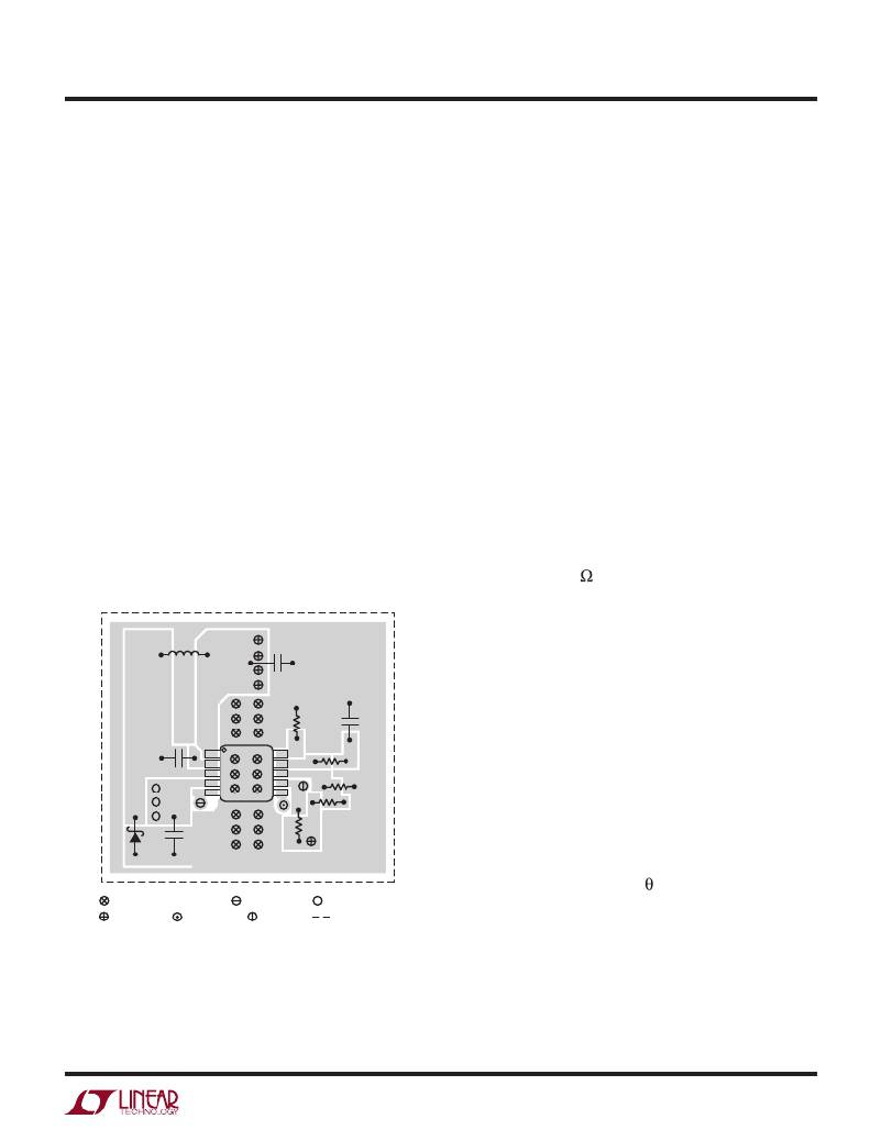
�PCB� Layout�
�For� proper� operation� and� minimum� EMI,� care� must� be�
�taken� during� printed� circuit� board� layout.� Figure� 9� shows�
�the� recommended� component� placement� with� trace,�
�ground� plane� and� via� locations.� Note� that� large,� switched�
�currents� flow� in� the� LT3480’s� V� IN� and� SW� pins,� the� catch�
�diode� (D1)� and� the� input� capacitor� (C1).� The� loop� formed�
�by� these� components� should� be� as� small� as� possible.� These�
�components,� along� with� the� inductor� and� output� capacitor,�
�should� be� placed� on� the� same� side� of� the� circuit� board,�
�and� their� connections� should� be� made� on� that� layer.� Place�
�a� local,� unbroken� ground� plane� below� these� components.�
�The� SW� and� BOOST� nodes� should� be� as� small� as� possible.�
�Finally,� keep� the� FB� and� V� C� nodes� small� so� that� the� ground�
�traces� will� shield� them� from� the� SW� and� BOOST� nodes.�
�The� Exposed� Pad� on� the� bottom� of� the� package� must� be�
�soldered� to� ground� so� that� the� pad� acts� as� a� heat� sink.� To�
�keep� thermal� resistance� low,� extend� the� ground� plane� as�
�much� as� possible,� and� add� thermal� vias� under� and� near�
�the� LT3480� to� additional� ground� planes� within� the� circuit�
�board� and� on� the� bottom� side.�
�L1�
�V� OUT�
�Hot� Plugging� Safely�
�The� small� size,� robustness� and� low� impedance� of� ceramic�
�capacitors� make� them� an� attractive� option� for� the� input�
�bypass� capacitor� of� LT3480� circuits.� However,� these� capaci-�
�tors� can� cause� problems� if� the� LT3480� is� plugged� into� a�
�live� supply� (see� Linear� Technology� Application� Note� 88� for�
�a� complete� discussion).� The� low� loss� ceramic� capacitor,�
�combined� with� stray� inductance� in� series� with� the� power�
�source,� forms� an� under� damped� tank� circuit,� and� the�
�voltage� at� the� V� IN� pin� of� the� LT3480� can� ring� to� twice� the�
�nominal� input� voltage,� possibly� exceeding� the� LT3480’s�
�rating� and� damaging� the� part.� If� the� input� supply� is� poorly�
�controlled� or� the� user� will� be� plugging� the� LT3480� into� an�
�energized� supply,� the� input� network� should� be� designed�
�to� prevent� this� overshoot.� Figure� 10� shows� the� waveforms�
�that� result� when� an� LT3480� circuit� is� connected� to� a� 24V�
�supply� through� six� feet� of� 24-gauge� twisted� pair.� The�
�first� plot� is� the� response� with� a� 4.7μF� ceramic� capacitor�
�at� the� input.� The� input� voltage� rings� as� high� as� 50V� and�
�the� input� current� peaks� at� 26A.� A� good� solution� is� shown�
�in� Figure� 10b.� A� 0.7� resistor� is� added� in� series� with� the�
�input� to� eliminate� the� voltage� overshoot� (it� also� reduces�
�the� peak� input� current).� A� 0.1μF� capacitor� improves� high�
�frequency� filtering.� For� high� input� voltages� its� impact� on�
�efficiency� is� minor,� reducing� efficiency� by� 1.5� percent� for�
�a� 5V� output� at� full� load� operating� from� 24V.�
�R� RT�
�C� C�
�High� Temperature� Considerations�
�VIAS� TO� V� OUT�
�VIAS� TO� PG�
�VIAS� TO� SYNC�
�R� C�
�R2�
�R1�
�D1� C1�
�GND� R� PG�
�3480� F09�
�VIAS� TO� LOCAL� GROUND� PLANE� VIAS� TO� RUN/SS� VIAS� TO� V� IN�
�OUTLINE� OF� LOCAL�
�GROUND� PLANE�
�Figure� 9.� A� Good� PCB� Layout� Ensures� Proper,� Low� EMI� Operation�
�The� PCB� must� provide� heat� sinking� to� keep� the� LT3480�
�cool.� The� exposed� pad� on� the� bottom� of� the� package� must�
�be� soldered� to� a� ground� plane.� This� ground� should� be� tied�
�to� large� copper� layers� below� with� thermal� vias;� these� lay-�
�ers� will� spread� the� heat� dissipated� by� the� LT3480.� Place�
�additional� vias� can� reduce� thermal� resistance� further.� With�
�these� steps,� the� thermal� resistance� from� die� (or� junction)�
�to� ambient� can� be� reduced� to� JA� =� 35°C/W� or� less.� With�
�100� LFPM� airflow,� this� resistance� can� fall� by� another� 25%.�
�Further� increases� in� airflow� will� lead� to� lower� thermal� re-�
�sistance.� Because� of� the� large� output� current� capability� of�
�3480fe�
�For� more� information� www.linear.com/LT3480�
�17�
�相关PDF资料 |
PDF描述 |
|---|---|
| RBC40DREF-S734 | CONN EDGECARD 80POS .100 EYELET |
| RBM30DCSI | CONN EDGECARD 60POS DIP .156 SLD |
| ASM08DTMN | CONN EDGECARD 16POS R/A .156 SLD |
| GSC31DRXN-S734 | CONN EDGECARD 62POS DIP .100 SLD |
| LT1376HVIS | IC REG BUCK ADJ 1.5A 16SOIC |
相关代理商/技术参数 |
参数描述 |
|---|---|
| LT3480IDD | 制造商:Linear Technology 功能描述:Conv DC-DC Single Step Down 3.6V to 36V 10-Pin DFN EP |
| LT3480IDD#PBF | 功能描述:IC REG BUCK ADJ 2A 10DFN RoHS:是 类别:集成电路 (IC) >> PMIC - 稳压器 - DC DC 开关稳压器 系列:- 设计资源:Design Support Tool 标准包装:1 系列:- 类型:升压(升压) 输出类型:固定 输出数:1 输出电压:3V 输入电压:0.75 V ~ 2 V PWM 型:- 频率 - 开关:- 电流 - 输出:100mA 同步整流器:是 工作温度:-40°C ~ 85°C 安装类型:表面贴装 封装/外壳:SOT-23-5 细型,TSOT-23-5 包装:剪切带 (CT) 供应商设备封装:TSOT-23-5 其它名称:AS1323-BTTT-30CT |
| LT3480IDD#TRPBF | 功能描述:IC REG BUCK ADJ 2A 10DFN RoHS:是 类别:集成电路 (IC) >> PMIC - 稳压器 - DC DC 开关稳压器 系列:- 设计资源:Design Support Tool 标准包装:1 系列:- 类型:升压(升压) 输出类型:固定 输出数:1 输出电压:3V 输入电压:0.75 V ~ 2 V PWM 型:- 频率 - 开关:- 电流 - 输出:100mA 同步整流器:是 工作温度:-40°C ~ 85°C 安装类型:表面贴装 封装/外壳:SOT-23-5 细型,TSOT-23-5 包装:剪切带 (CT) 供应商设备封装:TSOT-23-5 其它名称:AS1323-BTTT-30CT |
| LT3480IDDPBF | 制造商:Linear Technology 功能描述:DC-DC Converter Step-Down 3.6-36V DFN10 |
| LT3480IDD-PBF | 制造商:LINER 制造商全称:Linear Technology 功能描述:36V, 2A, 2.4MHz Step-Down Switching Regulator with 70μA Quiescent Current |
发布紧急采购,3分钟左右您将得到回复。