- 您现在的位置:买卖IC网 > PDF目录44986 > LT3688IFE#TRPBF (LINEAR TECHNOLOGY CORP) SWITCHING REGULATOR, PDSO24 PDF资料下载
参数资料
| 型号: | LT3688IFE#TRPBF |
| 厂商: | LINEAR TECHNOLOGY CORP |
| 元件分类: | 稳压器 |
| 英文描述: | SWITCHING REGULATOR, PDSO24 |
| 封装: | LEAD FREE, PLASTIC, TSSOP-24 |
| 文件页数: | 7/28页 |
| 文件大小: | 415K |
| 代理商: | LT3688IFE#TRPBF |
第1页第2页第3页第4页第5页第6页当前第7页第8页第9页第10页第11页第12页第13页第14页第15页第16页第17页第18页第19页第20页第21页第22页第23页第24页第25页第26页第27页第28页
LT3688
15
3688f
APPLICATIONS INFORMATION
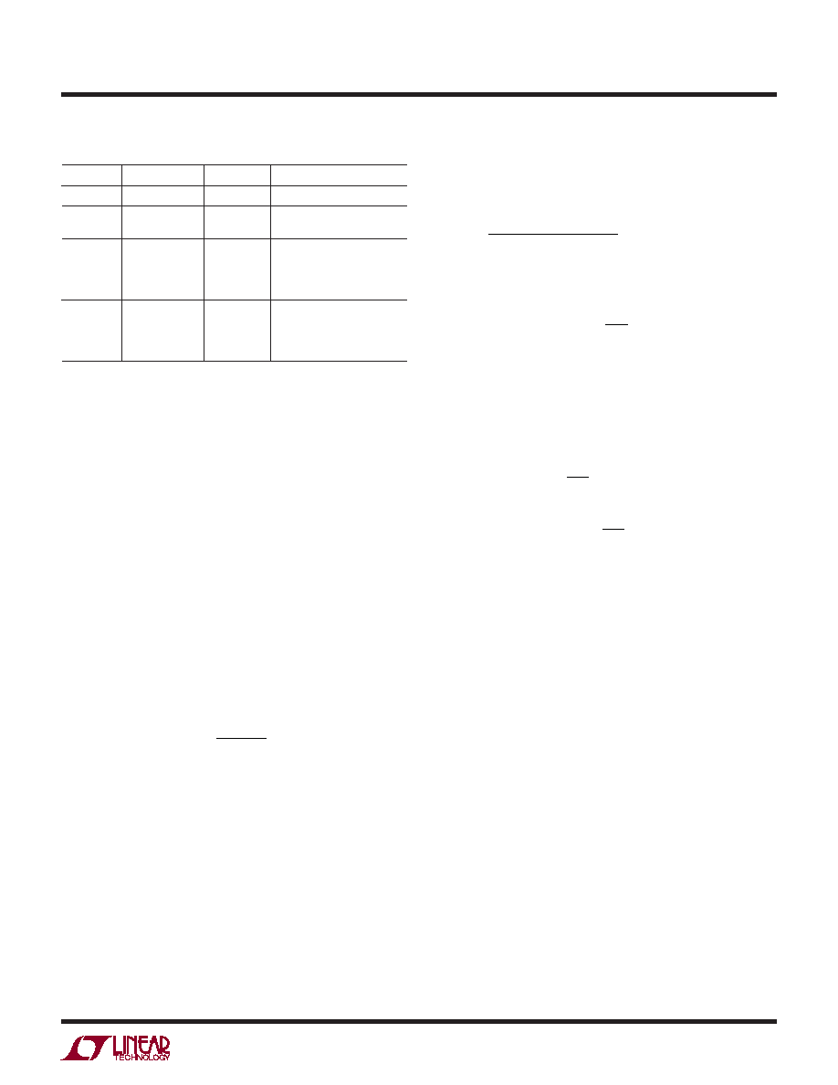
Table 2. Inductor Vendors
VENDOR
PART SERIES
TYPE
URL
Murata
LQH55D
Open
www.murata.com
TDK
SLF7045
SLF10145
Shielded
www.component.tdk.com
Toko
DC62CB
D63CB
D75C
D75F
Shielded
Open
www.toko.com
Sumida
CR54
CDRH74
CDRH6D38
CR75
Open
Shielded
Open
www.sumida.com
The optimum inductor for a given application may differ
from the one indicated by this simple design guide. A larger
value inductor provides a higher maximum load current,
and reduces the output voltage ripple. If your load is lower
than the maximum load current, then you can relax the
value of the inductor and operate with higher ripple current.
This allows you to use a physically smaller inductor, or
one with a lower DCR resulting in higher efciency. Be
aware that if the inductance differs from the simple rule
above, then the maximum load current will depend on
input voltage. In addition, low inductance may result in
discontinuous mode operation, which further reduces
maximum load current. Discontinuous operation occurs
when IOUT is less than ΔIL / 2. For details of maximum
output current and discontinuous mode operation, see
Linear Technology’s Application Note AN44. Finally, for
duty cycles greater than 50% (VOUT/VIN > 0.5), a minimum
inductance is required to avoid sub-harmonic oscillations:
LMIN = VOUT + VF
()
1.2MHz
fSW
where VF is the voltage drop of the catch diode (~0.4V),
fSW is in MHz, and LMIN is in μH.
The current in the inductor is a triangle wave with an average
value equal to the load current. The peak switch current
is equal to the output current plus half the peak-to-peak
inductor ripple current. The LT3688 limits its switch cur-
rent in order to protect itself and the system from overload
faults. Therefore, the maximum output current that the
LT3688 will deliver depends on the switch current limit,
the inductor value, and the input and output voltages.
When the switch is off, the potential across the induc-
tor is the output voltage plus the catch diode drop. This
gives the peak-to-peak ripple current in the inductor
ΔIL =
1– DC
() V
OUT + VF
()
Lf
where f is the switching frequency of the LT3688 and L is the
valueoftheinductor.Thepeakinductorandswitchcurrentis
ISW(PK) = IL(PK) = IOUT +
ΔIL
2
To maintain output regulation, this peak current must be
less than the LT3688’s switch current limit ILIM. ILIM is at
least 1.25A for at low duty cycles and decreases linearly
to 0.9A at DC = 0.9. The maximum output current is a
function of the chosen inductor value:
IOUT(MAX) = ILIM –
ΔIL
2
= 1.25A 1– 0.3DC
() –
ΔIL
2
Choosing an inductor value so that the ripple current is
small will allow a maximum output current near the switch
current limit.
One approach to choosing the inductor is to start with the
simple rule given above, look at the available inductors, and
choose one to meet cost or space goals. Then use these
equations to check that the LT3688 will be able to deliver
the required output current. Note again that these equations
assume that the inductor current is continuous.
Input Capacitor
Bypass the input of the LT3688 circuit with a ceramic
capacitor of an X7R or X5R type. Y5V types have poor
performance over temperature and applied voltage, and
should not be used. A 2.2μF to 4.7μF ceramic capacitor
is adequate to bypass the LT3688 and will easily handle
the ripple current. Note that larger input capacitance
is required when a lower switching frequency is used.
If the input power source has high impedance, or there
is signicant inductance due to long wires or cables,
相关PDF资料 |
PDF描述 |
|---|---|
| LT3688EUF#PBF | SWITCHING REGULATOR, PQCC24 |
| LT3688IFE#PBF | SWITCHING REGULATOR, PDSO24 |
| LT3688HFE#PBF | SWITCHING REGULATOR, PDSO24 |
| LT3688HFE#TRPBF | SWITCHING REGULATOR, PDSO24 |
| LT3689IUD-5#PBF | 1.95 A SWITCHING REGULATOR, 2160 kHz SWITCHING FREQ-MAX, PQCC16 |
相关代理商/技术参数 |
参数描述 |
|---|---|
| LT3688IUF#PBF | 功能描述:IC REG BUCK ADJ 0.8A DL 24QFN RoHS:是 类别:集成电路 (IC) >> PMIC - 稳压器 - DC DC 开关稳压器 系列:- 产品培训模块:MIC23xxx HyperLight Load™ Regulators 标准包装:5,000 系列:HyperLight Load® 类型:降压(降压) 输出类型:固定 输出数:1 输出电压:1.8V 输入电压:2.7 V ~ 5.5 V PWM 型:混合物 频率 - 开关:4MHz 电流 - 输出:2A 同步整流器:是 工作温度:-40°C ~ 125°C 安装类型:表面贴装 封装/外壳:8-VFDFN 裸露焊盘,8-MLF? 包装:带卷 (TR) 供应商设备封装:8-MLF?(2x2) 产品目录页面:1094 (CN2011-ZH PDF) 其它名称:576-3303-2 |
| LT3688IUF#TRPBF | 功能描述:IC REG BUCK ADJ 0.8A DL 24QFN RoHS:是 类别:集成电路 (IC) >> PMIC - 稳压器 - DC DC 开关稳压器 系列:- 设计资源:Design Support Tool 标准包装:1 系列:- 类型:升压(升压) 输出类型:固定 输出数:1 输出电压:3V 输入电压:0.75 V ~ 2 V PWM 型:- 频率 - 开关:- 电流 - 输出:100mA 同步整流器:是 工作温度:-40°C ~ 85°C 安装类型:表面贴装 封装/外壳:SOT-23-5 细型,TSOT-23-5 包装:剪切带 (CT) 供应商设备封装:TSOT-23-5 其它名称:AS1323-BTTT-30CT |
| LT3688IUFPBF | 制造商:LINER 制造商全称:Linear Technology 功能描述:Dual 800mA Step-Down Switching Regulator with Power-On Reset |
| LT3689 | 制造商:LINER 制造商全称:Linear Technology 功能描述:36V 500mA Step-Down Regulator and 200mA LDO |
| LT3689-5 | 制造商:LINER 制造商全称:Linear Technology 功能描述:700mA Step-Down Regulator with Power-On Reset and Watchdog Timer |
发布紧急采购,3分钟左右您将得到回复。