- 您现在的位置:买卖IC网 > PDF目录44988 > LT8415IDDB#PBF (LINEAR TECHNOLOGY CORP) 0.03 A SWITCHING REGULATOR, PDSO12 PDF资料下载
参数资料
| 型号: | LT8415IDDB#PBF |
| 厂商: | LINEAR TECHNOLOGY CORP |
| 元件分类: | 稳压器 |
| 英文描述: | 0.03 A SWITCHING REGULATOR, PDSO12 |
| 封装: | 3 X 2 MM, LEAD FREE, PLASTIC, DFN-12 |
| 文件页数: | 11/12页 |
| 文件大小: | 182K |
| 代理商: | LT8415IDDB#PBF |
LT8415
8
8415f
APPLICATIONS INFORMATION
Inductor Selection
Several inductors that work well with the LT8415 are listed
in Table 1. The tables are not complete, and there are many
other manufacturers and devices that can be used. Consult
each manufacturer for more detailed information and for
their entire selection of related parts, as many different
sizes and shapes are available.
Inductors with a value of 47μH or higher are recommended
for most LT8415 designs. Inductors with low core losses
and small DCR (copper wire resistance) are good choices
for LT8415 applications. For full output power, the induc-
tor should have a saturation current rating higher than
the peak inductor current. The peak inductor current can
be calculated as:
IPK = ILIMIT +
VIN 150 106
L
mA
where the worst case ILIMIT is 30mA. L is the inductance
value in Henrys and VIN is the input voltage to the boost
circuit.
Table 1. Recommended Inductors for LT8415
PART
L
(μH)
DCR
(μH)
SIZE
(mm)
VENDOR
LQH2MCN680K02
LQH32CN101K53
68
100
6.6
3.5
2.0 × 1.6 × 0.9
3.2 × 2.5 × 2.0
Murata
www.murata.com
DO2010-683ML
DO2010-104ML
LPS3015-104ML
LPS3015-154ML
68
100
150
8.8
15.7
3.4
6.1
2.0 × 2.0 × 1.0
3.0 × 3.0 × 1.4
Coilcraft
www.coilcraft.com
Capacitor Selection
The small size and low ESR of ceramic capacitors make
them suitable for most LT8415 applications. X5R and
X7R types are recommended because they retain their
capacitance over wider voltage and temperature ranges
than other types such as Y5V or Z5U. A 2.2μF or higher
input capacitor and a 0.1μF to 1μF output capacitor are
sufcient for most applications. Always use a capacitor
with a sufcient voltage rating. Many ceramic capacitors
rated at 0.1μF to 1μF have greatly reduced capacitance
when bias voltages are applied. Be sure to check actual
capacitance at the desired output voltage. Generally a 0603
or 0805 size capacitor will be adequate. A 0.1μF to 1μF
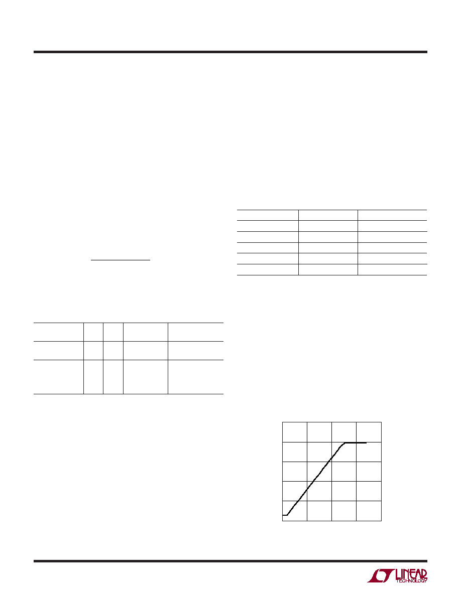
FBP VOLTAGE (V)
0
OUTPUT
VOL
TAGE
(V)
50
40
30
10
20
0
8415 F01
2
1
1.5
0.5
Figure 1. FBP to VOUT Transfer Curve
capacitor placed on the CAP node is recommended to lter
the inductor current while a 0.1μF to 1μF capacitor placed
on the VOUT node will give excellent transient response
and stability. To make the VREF pin less sensitive to noise,
putting a capacitor on the VREF pin is recommended, but
not required. A 47nF to 220nF 0402 capacitor will be suf-
cient. See also Soft-Start section for more information
about a capacitor across VREF.Table2showsalistofseveral
capacitor manufacturers. Consult the manufacturers for
more detailed information and for their entire selection
of related parts.
Table 2. Recommended Ceramic Capacitor Manufacturers
MANUFACTURER
PHONE
WEBSITE
Taiyo Yuden
(408) 573-4150
www.t-yuden.com
Murata
(814) 237-1431
www.murata.com
AVX
(843) 448-9411
www.avxcorp.com
Kemet
(408)986-0424
www.kemet.com
TDK
(847) 803-6100
www.tdk.com
Setting Output Voltage
The output voltage is set by the FBP pin voltage, and VOUT
is equal to 31.85 VFBP when the output is regulated,
shown in Figure 1. Since the VREF pin provides a good
reference (~1.235V), the FBP voltage can be easily set by
a resistor divider from the VREF pin to ground. The series
resistance of this resistor divider should be kept larger than
200KΩ to prevent loading down the VREF pin. The FBP pin
can also be biased directly by an external reference. For
over voltage protection, the output voltage is limited to
40V. Therefore, if VFBP is higher than 1.235V, the output
voltage will stay at 40V.
相关PDF资料 |
PDF描述 |
|---|---|
| LT8415EDDB#TRMPBF | 0.03 A SWITCHING REGULATOR, PDSO12 |
| LT8415IDDB#TRPBF | 0.03 A SWITCHING REGULATOR, PDSO12 |
| LTC1043MD/883B | SPECIALTY ANALOG CIRCUIT, CDIP18 |
| LTC1146ACN | SPECIALTY ANALOG CIRCUIT, PDIP18 |
| LTC1148HVCS-3.3#TR | SWITCHING CONTROLLER, 250 kHz SWITCHING FREQ-MAX, PDSO14 |
相关代理商/技术参数 |
参数描述 |
|---|---|
| LT8500EUHH#PBF | 功能描述:IC PWM GENERATOR 56-QFN RoHS:是 类别:集成电路 (IC) >> 时钟/计时 - 专用 系列:- 标准包装:1 系列:- 类型:时钟/频率发生器,多路复用器 PLL:是 主要目的:存储器,RDRAM 输入:晶体 输出:LVCMOS 电路数:1 比率 - 输入:输出:1:2 差分 - 输入:输出:无/是 频率 - 最大:400MHz 电源电压:3 V ~ 3.6 V 工作温度:0°C ~ 85°C 安装类型:表面贴装 封装/外壳:16-TSSOP(0.173",4.40mm 宽) 供应商设备封装:16-TSSOP 包装:Digi-Reel® 其它名称:296-6719-6 |
| LT8500EUHH#TRPBF | 功能描述:IC PWM GENERATOR 56-QFN RoHS:是 类别:集成电路 (IC) >> 时钟/计时 - 专用 系列:- 标准包装:28 系列:- 类型:时钟/频率发生器 PLL:是 主要目的:Intel CPU 服务器 输入:时钟 输出:LVCMOS 电路数:1 比率 - 输入:输出:3:22 差分 - 输入:输出:无/是 频率 - 最大:400MHz 电源电压:3.135 V ~ 3.465 V 工作温度:0°C ~ 85°C 安装类型:表面贴装 封装/外壳:64-TFSOP (0.240",6.10mm 宽) 供应商设备封装:64-TSSOP 包装:管件 |
| LT8500IUHH#PBF | 功能描述:IC PWM GENERATOR 56-QFN RoHS:是 类别:集成电路 (IC) >> 时钟/计时 - 专用 系列:- 标准包装:28 系列:- 类型:时钟/频率发生器 PLL:是 主要目的:Intel CPU 服务器 输入:时钟 输出:LVCMOS 电路数:1 比率 - 输入:输出:3:22 差分 - 输入:输出:无/是 频率 - 最大:400MHz 电源电压:3.135 V ~ 3.465 V 工作温度:0°C ~ 85°C 安装类型:表面贴装 封装/外壳:64-TFSOP (0.240",6.10mm 宽) 供应商设备封装:64-TSSOP 包装:管件 |
| LT8500IUHH#TRPBF | 功能描述:IC PWM GENERATOR 56-QFN RoHS:是 类别:集成电路 (IC) >> 时钟/计时 - 专用 系列:- 标准包装:28 系列:- 类型:时钟/频率发生器 PLL:是 主要目的:Intel CPU 服务器 输入:时钟 输出:LVCMOS 电路数:1 比率 - 输入:输出:3:22 差分 - 输入:输出:无/是 频率 - 最大:400MHz 电源电压:3.135 V ~ 3.465 V 工作温度:0°C ~ 85°C 安装类型:表面贴装 封装/外壳:64-TFSOP (0.240",6.10mm 宽) 供应商设备封装:64-TSSOP 包装:管件 |
| LT-8501M | 制造商:Mencom 功能描述: |
发布紧急采购,3分钟左右您将得到回复。