- 您现在的位置:买卖IC网 > PDF目录44988 > LTC1148HVCS-5#TR (LINEAR TECHNOLOGY CORP) SWITCHING CONTROLLER, 250 kHz SWITCHING FREQ-MAX, PDSO14 PDF资料下载
参数资料
| 型号: | LTC1148HVCS-5#TR |
| 厂商: | LINEAR TECHNOLOGY CORP |
| 元件分类: | 稳压器 |
| 英文描述: | SWITCHING CONTROLLER, 250 kHz SWITCHING FREQ-MAX, PDSO14 |
| 封装: | 0.150 INCH, PLASTIC, SOP-14 |
| 文件页数: | 3/20页 |
| 文件大小: | 237K |
| 代理商: | LTC1148HVCS-5#TR |
11
LTC1148
LTC1148-3.3/LTC1148-5
114835fd
APPLICATIO S I FOR ATIO
W
UU
U
In surface mount applications multiple capacitors may
have to be paralleled to meet the capacitance, ESR, or
RMS current handling requirements of the application.
Aluminum electrolytic and dry tantalum capacitors are
both available in surface mount configurations. In the
case of tantalum, it is critical that the capacitors are surge
tested for use in switching power supplies. An excellent
choice is the AVX TPS series of surface mount tantalums,
available in case heights ranging from 2mm to 4mm. For
example, if 200F/10V is called for in an application
requiring 3mm height, two AVX 100F/10V (P/N TPSD
107K010) could be used. Consult the manufacturer for
other specific recommendations.
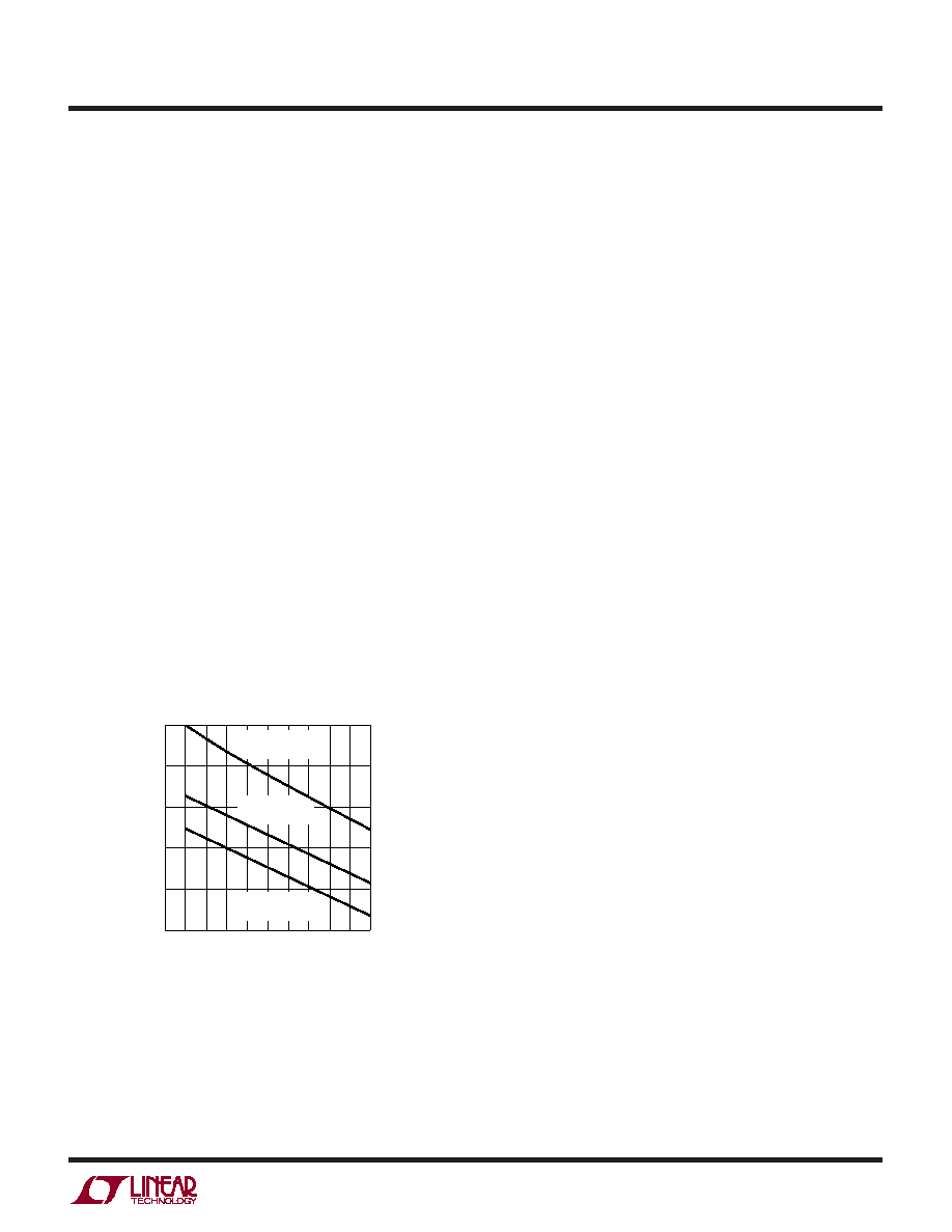
At low supply voltages, a minimum capacitance at COUT
is needed to prevent an abnormal low frequency oper-
ating mode (see Figure 4). When COUT is made too
small, the output ripple at low frequencies will be large
enough to trip the voltage comparator. This causes
Burst Modeoperation to be activated when the LTC1148
series would normally be in continuous operation. The
effect is most pronounced with low values of RSENSE
and can be improved by operating at higher frequencies
with lower values of L. The output remains in regulation
at all times.
several cycles to respond to a step in DC (resistive) load
current. When a load step occurs, VOUT shifts by an
amount equal to ILOAD ESR, where ESR is the effective
series resistance of COUT. ILOAD also begins to charge
or discharge COUT until the regulator loop adapts to the
current change and returns VOUT to its steady state
value. During this recovery time VOUT can be monitored
for overshoot or ringing which would indicate a stability
problem. The Pin 6 external components shown in the
Figure 1 circuit will prove adequate compensation for
most applications.
A second, more severe transient is caused by switching in
loads with large (>1F) supply bypass capacitors. The
discharged bypass capacitors are effectively put in parallel
with COUT, causing a rapid drop in VOUT. No regulator can
deliver enough current to prevent this problem if the load
switch resistance is low and it is driven quickly. The only
solution is to limit the rise time of the switch drive so that
the load rise time is limited to approximately 25 CLOAD.
Thus a 10F capacitor would require a 250s rise time,
limiting the charging current to about 200mA.
Efficiency Considerations
The percent efficiency of a switching regulator is equal to
the output power divided by the input power times 100%.
It is often useful to analyze individual losses to determine
what is limiting the efficiency and which change would
produce the most improvement. Percent efficiency can be
expressed as:
%Efficiency = 100% – (L1 + L2 + L3 + ...)
where L1, L2, etc., are the individual losses as a percent-
age of input power. (For high efficiency circuits only small
errors are incurred by expressing losses as a percentage
of output power).
Although all dissipative elements in the circuit produce
losses, three main sources usually account for most of the
losses in LTC1148 series circuits: 1) LTC1148 DC bias
current, 2) MOSFET gate charge current, and 3) I
2R
losses.
1. The DC supply current is the current which flows into
VIN Pin 3 less the gate charge current. For VIN = 10V the
Checking Transient Response
The regulator loop response can be checked by looking
at the load transient response. Switching regulators take
(VIN – VOUT) VOLTAGE (V)
0
C
OUT
(
F) 600
1000
4
LTC1148 F04
400
200
0
1
2
3
5
800
L = 50H
RSENSE = 0.02
L = 25H
RSENSE = 0.02
L = 50H
RSENSE = 0.05
Figure 4. Minimum Value of COUT
相关PDF资料 |
PDF描述 |
|---|---|
| LTC1149CN-5#PBF | SWITCHING CONTROLLER, 250 kHz SWITCHING FREQ-MAX, PDIP16 |
| LTC1266CS#TR-3.3 | SWITCHING CONTROLLER, 400 kHz SWITCHING FREQ-MAX, PDSO16 |
| LTC1266IS#TR-3.3 | SWITCHING CONTROLLER, 400 kHz SWITCHING FREQ-MAX, PDSO16 |
| LTC1266IS#TR-5 | SWITCHING CONTROLLER, 400 kHz SWITCHING FREQ-MAX, PDSO16 |
| LTC1266IS-5 | SWITCHING CONTROLLER, 400 kHz SWITCHING FREQ-MAX, PDSO16 |
相关代理商/技术参数 |
参数描述 |
|---|---|
| LTC1148HVIS-5 | 功能描述:IC REG CTRLR BUCK PWM CM 14-SOIC RoHS:否 类别:集成电路 (IC) >> PMIC - 稳压器 - DC DC 切换控制器 系列:- 标准包装:4,500 系列:PowerWise® PWM 型:控制器 输出数:1 频率 - 最大:1MHz 占空比:95% 电源电压:2.8 V ~ 5.5 V 降压:是 升压:无 回扫:无 反相:无 倍增器:无 除法器:无 Cuk:无 隔离:无 工作温度:-40°C ~ 125°C 封装/外壳:6-WDFN 裸露焊盘 包装:带卷 (TR) 配用:LM1771EVAL-ND - BOARD EVALUATION LM1771 其它名称:LM1771SSDX |
| LTC1148HVIS-5#PBF | 功能描述:IC REG CTRLR BUCK PWM CM 14-SOIC RoHS:是 类别:集成电路 (IC) >> PMIC - 稳压器 - DC DC 切换控制器 系列:- 标准包装:4,500 系列:PowerWise® PWM 型:控制器 输出数:1 频率 - 最大:1MHz 占空比:95% 电源电压:2.8 V ~ 5.5 V 降压:是 升压:无 回扫:无 反相:无 倍增器:无 除法器:无 Cuk:无 隔离:无 工作温度:-40°C ~ 125°C 封装/外壳:6-WDFN 裸露焊盘 包装:带卷 (TR) 配用:LM1771EVAL-ND - BOARD EVALUATION LM1771 其它名称:LM1771SSDX |
| LTC1148HVIS-5#TR | 功能描述:IC REG CTRLR BUCK PWM CM 14-SOIC RoHS:否 类别:集成电路 (IC) >> PMIC - 稳压器 - DC DC 切换控制器 系列:- 标准包装:4,500 系列:PowerWise® PWM 型:控制器 输出数:1 频率 - 最大:1MHz 占空比:95% 电源电压:2.8 V ~ 5.5 V 降压:是 升压:无 回扫:无 反相:无 倍增器:无 除法器:无 Cuk:无 隔离:无 工作温度:-40°C ~ 125°C 封装/外壳:6-WDFN 裸露焊盘 包装:带卷 (TR) 配用:LM1771EVAL-ND - BOARD EVALUATION LM1771 其它名称:LM1771SSDX |
| LTC1148HVIS-5#TRPBF | 功能描述:IC REG CTRLR BUCK PWM CM 14-SOIC RoHS:是 类别:集成电路 (IC) >> PMIC - 稳压器 - DC DC 切换控制器 系列:- 标准包装:4,500 系列:PowerWise® PWM 型:控制器 输出数:1 频率 - 最大:1MHz 占空比:95% 电源电压:2.8 V ~ 5.5 V 降压:是 升压:无 回扫:无 反相:无 倍增器:无 除法器:无 Cuk:无 隔离:无 工作温度:-40°C ~ 125°C 封装/外壳:6-WDFN 裸露焊盘 包装:带卷 (TR) 配用:LM1771EVAL-ND - BOARD EVALUATION LM1771 其它名称:LM1771SSDX |
| LTC1148L | 制造商:LINER 制造商全称:Linear Technology 功能描述:High Efficiency Synchronous Step-Down Switching Regulators |
发布紧急采购,3分钟左右您将得到回复。