- 您现在的位置:买卖IC网 > PDF目录11032 > LTC1164-7CSW#PBF (Linear Technology)IC FILTR 8TH ORDR LOWPASS 16SOIC PDF资料下载
参数资料
| 型号: | LTC1164-7CSW#PBF |
| 厂商: | Linear Technology |
| 文件页数: | 10/16页 |
| 文件大小: | 0K |
| 描述: | IC FILTR 8TH ORDR LOWPASS 16SOIC |
| 标准包装: | 47 |
| 滤波器类型: | 线性相位,低通开关电容器 |
| 频率 - 截止或中心: | 100kHz |
| 滤波器数: | 1 |
| 滤波器阶数: | 8th |
| 电源电压: | 4.75 V ~ 16 V,±2.375 V ~ 8 V |
| 安装类型: | 表面贴装 |
| 封装/外壳: | 16-SOIC(0.295",7.50mm 宽) |
| 供应商设备封装: | 16-SOIC |
| 包装: | 管件 |
| 产品目录页面: | 1324 (CN2011-ZH PDF) |
3
LTC1164-7
11647fb
ELECTRICAL C
C
HARA TERISTICS
PARAMETER
CONDITIONS
MIN
TYP
MAX
UNITS
Group Delay (td)(fCLK/fC) = 50:1, f ≥ fCUTOFF
151.0
± 1
s
td = (1/360)(f/fC)(fCLK/fC) = 100:1, f ≥ fCUTOFF
297.2
± 1
s
(Note 3)
(fCLK/fC) = 50:1, f ≥ fCUTOFF
●
149.3
153.5
s
(fCLK/fC) = 100:1, f ≥ fCUTOFF
●
293.8
301.4
s
Group Delay Deviation
(fCLK/fC) = 50:1, f ≥ fCUTOFF
±1.0
%
(Note 3)
(fCLK/fC) = 100:1, f ≥ fCUTOFF
±1.0
%
(fCLK/fC) = 50:1, f ≥ fCUTOFF
●
±2.0
%
(fCLK/fC) = 100:1, f ≥ fCUTOFF
●
±2.5
%
Input Frequency Range (Table 9)
(fCLK/fC) = 50:1
<fCLK
kHz
(fCLK/fC) = 100:1
<fCLK/2
kHz
Maximum fCLK
VS = Single 5V (Pins 3 and 5 at 2V)
1
MHz
VS = ±5V
1
MHz
VS = ±7.5V
1
MHz
Clock Feedthrough (f = fCLK)
50:1,
±5V, Input at GND
100
VRMS
Wideband Noise
VS = ±2.5V
95
± 5%
VRMS
(1Hz
≤ f < fCLK)VS = ±5V
105
± 5%
VRMS
VS = ±7.5V
115
± 5%
VRMS
Input Impedance
35
55
90
k
Output DC Voltage Swing (Note 4)
VS = ±2.375V
±1.25
±1.4
V
VS = ±5V
●
±3.70
±3.9
V
VS = ±7.5V
●
±5.40
±6.1
V
Output DC Offset
50:1, VS = ±5V
±100
±220
mV
100:1, VS = ±5V
±100
mV
Output DC Offset TempCo
50:1, VS = ±5V
±200
V/°C
100:1, VS = ±5V
±200
V/°C
Power Supply Current
VS = ±2.375V, TA = 25°C
2.5
4.0
mA
●
4.5
mA
VS = ±5V, TA = 25°C
4.5
7.0
mA
●
8.0
mA
VS = ±7.5V, TA = 25°C
7.0
11.0
mA
●
12.5
mA
Power Supply Range
±2.375
±8V
Note 1: Absolute Maximum Ratings are those values beyond which the life of a
device may be impaired.
Note 2: Input frequencies, f, are linearly phase shifted through the filter as long as
f
≤ fC; fC = cutoff frequency.
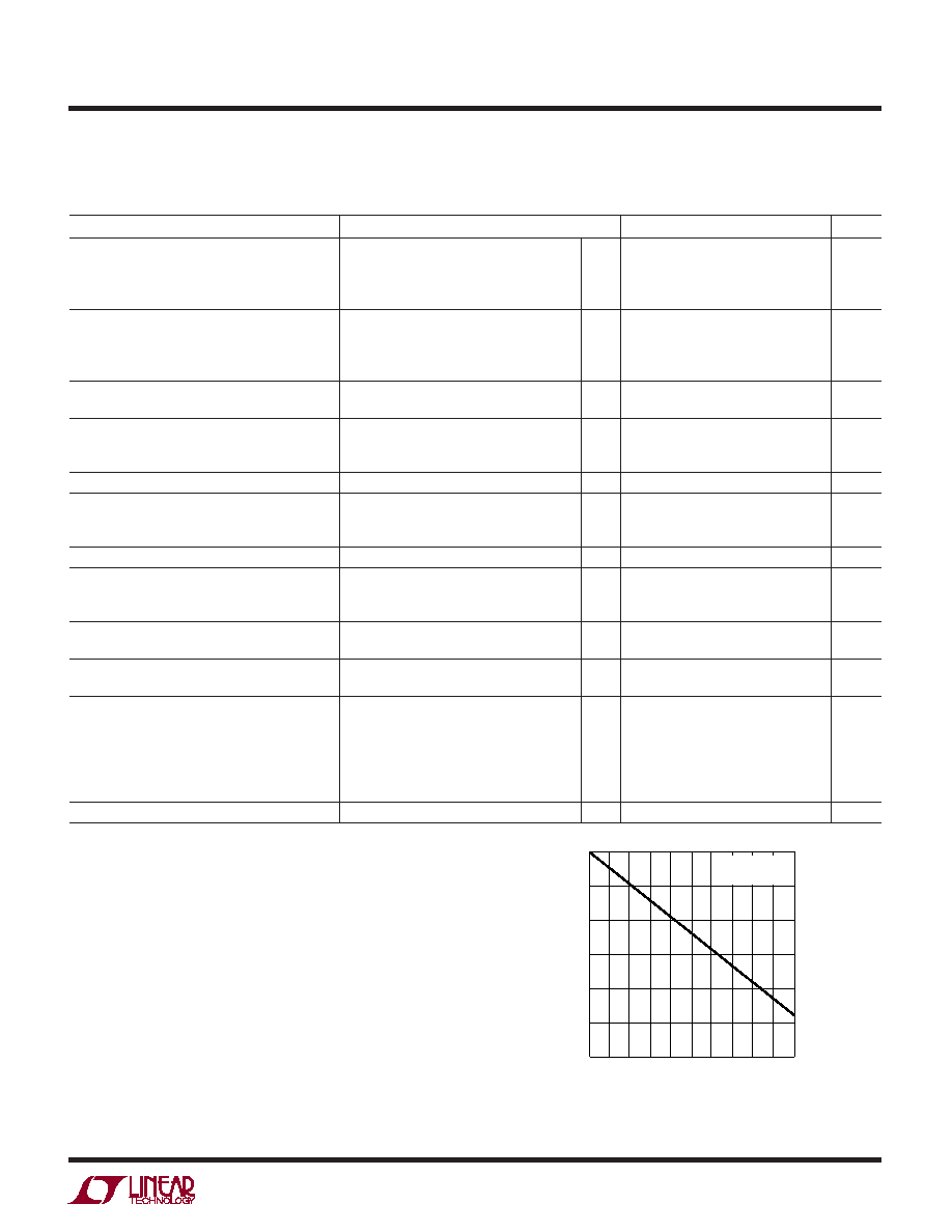
Figure 1 curve shows the typical phase response of an LTC1164-7 operating at
fCLK = 400kHz, fC = 8kHz and it closely matches an ideal straight line. The phase
shift is described by: phase shift = 180
° – F (f/fC); f ≤ fC.
F is arbitrarily called the “phase factor” expressed in degrees. The phase factor
together with the specified deviation from the ideal straight line allows the
calculation of the phase at a given frequency. Example: The phase shift at 7kHz of
the LTC1164-7 shown in Figure 1 is: phase shift = 180
° – 434° (7kHz/10kHz) ±
nonlinearity = –123.8
° ± 1% or –123.9°± 1.24°.
Note 3: Group delay and group delay deviation are calculated from the measured
phase factor and phase deviation specifications.
Note 4: The AC swing is typically 11VP-P, 7VP-P, 2.8VP-P for ±7.5V, ±5V, ±2.5V
supply respectively. For more information refer to the THD + Noise vs Input graphs.
Figure 1. Phase Response in the Passband (Note 1)
The
● denotes the specifications which apply over the full operating
temperature range, otherwise specifications are at TA = 25°C. VS = ±7.5V, RL = 10k, fCUTOFF = 8kHz or 4kHz, fCLK = 400kHz, TTL or CMOS
level and all gain measurements are referenced to passband gain, unless otherwise specified. (Maximum clock rise or fall time
≤ 1s.)
The filter cutoff frequency is abbreviated as fCUTOFF or fC.
FREQUENCY (kHz)
0
–360
PHASE
(DEG)
–270
–180
–90
0
90
180
246
8
1164-7 F01
10
13
57
9
fCLK = 500kHz
(fCLK/fC) = 50:1
相关PDF资料 |
PDF描述 |
|---|---|
| LTC1562IG#PBF | IC FILTER UNIV RC QUAD LN 20SSOP |
| LTC1064-3CSW#PBF | IC FILTR 8TH ORDR LOWPASS 16SOIC |
| VE-243-IY-F1 | CONVERTER MOD DC/DC 24V 50W |
| VE-210-IY-F4 | CONVERTER MOD DC/DC 5V 50W |
| MAX297CPA+ | IC FILTER LOWPASS 8TH 8-DIP |
相关代理商/技术参数 |
参数描述 |
|---|---|
| LTC1164-7M | 制造商:LINER 制造商全称:Linear Technology 功能描述:Low Power, Linear Phase 8th Order Lowpass Filter |
| LTC1164-7M/883 | 制造商:未知厂家 制造商全称:未知厂家 功能描述:Analog Filter |
| LTC1164-7MJ | 制造商:Linear Technology 功能描述:Active Filter Single Low Pass 8th Order 20kHz 14-Pin CDIP |
| LTC1164-8 | 制造商:LINER 制造商全称:Linear Technology 功能描述:Ultraselective, Low Power 8th Order Elliptic Bandpass Filter with Adjustable Gain |
| LTC1164-8_09 | 制造商:LINER 制造商全称:Linear Technology 功能描述:Ultraselective, Low Power 8th Order Elliptic Bandpass Filter with Adjustable Gain |
发布紧急采购,3分钟左右您将得到回复。