- 您现在的位置:买卖IC网 > PDF目录11022 > LTC1164ACN (Linear Technology)IC FILTER BUILDING BLOCK 24-DIP PDF资料下载
参数资料
| 型号: | LTC1164ACN |
| 厂商: | Linear Technology |
| 文件页数: | 15/16页 |
| 文件大小: | 0K |
| 描述: | IC FILTER BUILDING BLOCK 24-DIP |
| 标准包装: | 15 |
| 滤波器类型: | 通用开关电容器 |
| 频率 - 截止或中心: | 20kHz |
| 滤波器数: | 4 |
| 滤波器阶数: | 8th |
| 电源电压: | ±2.37 V ~ 8 V |
| 安装类型: | 通孔 |
| 封装/外壳: | 24-DIP(0.300",7.62mm) |
| 供应商设备封装: | 24-PDIP |
| 包装: | 管件 |
LTC1164
8
1164fa
ANALOG CONSIDERATIONS
1. Grounding and Bypassing
The LTC1164 should be used with separated analog
and digital ground planes and single point grounding
techniques.
Pin 6 (AGND) should be tied directly to the analog ground
plane.
Pin 7 (V+) should be bypassed to the ground plane with a
0.1F ceramic disk with leads as short as possible. Pin 19
(V–) should be bypassed with a 0.1F ceramic disk. For
single supply applications, V– can be tied to the analog
ground plane.
For good noise performance, V+ and V– must be free of
noise and ripple.
All analog inputs should be referenced directly to the
single point ground. The clock inputs should be shielded
from and/or routed away from the analog circuitry and a
separate digital ground plane used.
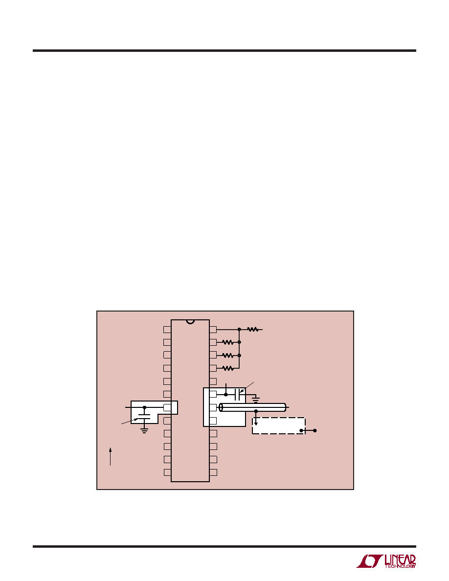
Figure 3 shows an example of an ideal ground plane design
for a two sided board. Of course this much ground
plane will not always be possible, but users should strive
to get as close to this as possible. Proto boards are not
recommended.
2. Buffering the Filter Output
When driving coaxial cables and 1x scope probes, the filter
output should be buffered. This is important
especially when high Qs are used to design a specific filter.
Inadequate buffering may cause errors in noise,
distortion, Q, and gain measurements. When 10x probes
are used, buffering is usually not required. A buffer is
recommended especially when THD tests are performed.
As shown in Figure 4, the buffer should be adequately
bypassed to minimize clock feedthrough.
Figure 3. Example Ground Plane Breadboard Technique for LTC1164
APPLICATIO S I FOR ATIO
WU
UU
LTC1164 AI01
DIGITAL GROUND
PLANE
ANALOG
GROUND
PLANE
7.5V
–7.5V
VIN
0.1F CERAMIC DISK
0.1F
CERAMIC
DISK
CLOCK
(SINGLE POINT
GROUND)
NOTE: CONNECT ANALOG AND DIGITAL
GROUND PLANES AT A SINGLE POINT AT
THE BOARD EDGE
FOR BEST HIGH FREQUENCY RESPONSE
PLACE RESISTORS PARALLEL TO DOUBLE
SIDED COPPER CLAD BOARD AND LAY FLAT
(4 RESISTORS SHOWN HERE TYPICAL)
1
2
3
4
5
6
10
11
12
24
23
22
15
14
13
PIN 1 DENT
7
21
20
18
17
8
9
16
19
相关PDF资料 |
PDF描述 |
|---|---|
| MC9S08SE8VTG | MCU 8BIT 8K FLASH 5V 16-TSSOP |
| MC9S08FL8CLC | MCU 8BIT 8K FLASH 32-LQFP |
| MC9S08SE4MWL | MCU 8BIT 4K FLASH 5V 28-SOIC |
| LTC1264-7CN#PBF | IC FILTER 8TH ORDR LOWPASS 14DIP |
| MC9S08SH4CSC | IC MCU 8BIT 4K FLASH 8-SOIC |
相关代理商/技术参数 |
参数描述 |
|---|---|
| LTC1164ACN#PBF | 功能描述:IC FILTER BUILDING BLOCK 24-DIP RoHS:是 类别:集成电路 (IC) >> 接口 - 滤波器 - 有源 系列:- 产品培训模块:Lead (SnPb) Finish for COTS Obsolescence Mitigation Program 标准包装:1,000 系列:- 滤波器类型:连续时间,带通低通 频率 - 截止或中心:150kHz 滤波器数:4 滤波器阶数:8th 电源电压:4.74 V ~ 11 V,±2.37 V ~ 5.5 V 安装类型:表面贴装 封装/外壳:28-SOIC(0.295",7.50mm 宽) 供应商设备封装:28-SOIC W 包装:带卷 (TR) |
| LTC1164ACS | 制造商:LINER 制造商全称:Linear Technology 功能描述:Low Power, Low Noise, Quad Universal Filter Building Block |
| LTC1164ACSW | 功能描述:IC FILTER BUILDING BLOCK 24-SOIC RoHS:否 类别:集成电路 (IC) >> 接口 - 滤波器 - 有源 系列:- 产品培训模块:Lead (SnPb) Finish for COTS Obsolescence Mitigation Program 标准包装:1,000 系列:- 滤波器类型:连续时间,带通低通 频率 - 截止或中心:150kHz 滤波器数:4 滤波器阶数:8th 电源电压:4.74 V ~ 11 V,±2.37 V ~ 5.5 V 安装类型:表面贴装 封装/外壳:28-SOIC(0.295",7.50mm 宽) 供应商设备封装:28-SOIC W 包装:带卷 (TR) |
| LTC1164ACSW#PBF | 功能描述:IC FILTER BUILDING BLOCK 24-SOIC RoHS:是 类别:集成电路 (IC) >> 接口 - 滤波器 - 有源 系列:- 产品培训模块:Lead (SnPb) Finish for COTS Obsolescence Mitigation Program 标准包装:1,000 系列:- 滤波器类型:连续时间,带通低通 频率 - 截止或中心:150kHz 滤波器数:4 滤波器阶数:8th 电源电压:4.74 V ~ 11 V,±2.37 V ~ 5.5 V 安装类型:表面贴装 封装/外壳:28-SOIC(0.295",7.50mm 宽) 供应商设备封装:28-SOIC W 包装:带卷 (TR) |
| LTC1164ACSW#TR | 功能描述:IC FILTER LP 2ND ORD QUAD 24SOIC RoHS:否 类别:集成电路 (IC) >> 接口 - 滤波器 - 有源 系列:- 产品培训模块:Lead (SnPb) Finish for COTS Obsolescence Mitigation Program 标准包装:1,000 系列:- 滤波器类型:连续时间,带通低通 频率 - 截止或中心:150kHz 滤波器数:4 滤波器阶数:8th 电源电压:4.74 V ~ 11 V,±2.37 V ~ 5.5 V 安装类型:表面贴装 封装/外壳:28-SOIC(0.295",7.50mm 宽) 供应商设备封装:28-SOIC W 包装:带卷 (TR) |
发布紧急采购,3分钟左右您将得到回复。