- 您现在的位置:买卖IC网 > PDF目录14798 > LTC1475IS8#PBF (Linear Technology)IC REG BUCK ADJ 0.75A 8SOIC PDF资料下载
参数资料
| 型号: | LTC1475IS8#PBF |
| 厂商: | Linear Technology |
| 文件页数: | 8/20页 |
| 文件大小: | 0K |
| 描述: | IC REG BUCK ADJ 0.75A 8SOIC |
| 标准包装: | 100 |
| 类型: | 降压(降压) |
| 输出类型: | 可调式 |
| 输出数: | 1 |
| 输出电压: | 可调 |
| 输入电压: | 3 V ~ 18 V |
| PWM 型: | Burst Mode? |
| 电流 - 输出: | 750mA |
| 同步整流器: | 无 |
| 工作温度: | -40°C ~ 85°C |
| 安装类型: | 表面贴装 |
| 封装/外壳: | 8-SOIC(0.154",3.90mm 宽) |
| 包装: | 管件 |
| 供应商设备封装: | 8-SOIC |
�� �
�
�LTC1474/LTC1475�
�APPLICATIO� N� S� I� N� FOR� M� ATIO� N�
�If� the� L� MIN� calculated� is� not� practical,� a� larger� I� PEAK� should�
�be� used.� Although� the� above� equation� provides� the� mini-�
�mum,� better� performance� (efficiency,� line/load� regulation,�
�noise)� is� usually� gained� with� higher� values.� At� higher�
�inductances,� peak� current� and� frequency� decrease� (im-�
�proving� efficiency)� and� inductor� ripple� current� decreases�
�(improving� noise� and� line/load� regulation).� For� a� given�
�inductor� type,� however,� as� inductance� is� increased,� DC�
�resistance� (DCR)� increases,� increasing� copper� losses,�
�and� current� rating� decreases,� both� effects� placing� an�
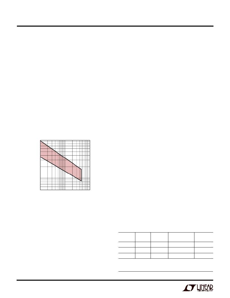
�upper� limit� on� the� inductance.� The� recommended� range� of�
�inductances� for� small� surface� mount� inductors� as� a� func-�
�tion� of� peak� current� is� shown� in� Figure� 3.� The� values� in� this�
�range� are� a� good� compromise� between� the� trade-offs�
�discussed� above.� If� space� is� not� a� premium,� inductors� with�
�larger� cores� can� be� used,� which� extends� the� recom-�
�mended� range� of� Figure� 3� to� larger� values.�
�1000�
�500�
�100�
�section,� increased� inductance� requires� more� turns� of� wire�
�and� therefore� copper� losses� will� increase.�
�Ferrite� and� Kool� M� μ� designs� have� very� low� core� loss� and�
�are� preferred� at� high� switching� frequencies,� so� design�
�goals� can� concentrate� on� copper� loss� and� preventing�
�saturation.� Ferrite� core� material� saturates� “hard,”� which�
�means� that� inductance� collapses� abruptly� when� the� peak�
�design� current� is� exceeded.� This� results� in� an� abrupt�
�increase� in� inductor� current� above� I� PEAK� and� consequent�
�increase� in� voltage� ripple.� Do� not� allow� the� core� to� satu-�
�rate!� Coiltronics,� Coilcraft,� Dale� and� Sumida� make� high�
�performance� inductors� in� small� surface� mount� packages�
�with� low� loss� ferrite� and� Kool� M� μ� cores� and� work� well� in�
�LTC1474/LTC1475� regulators.�
�Catch� Diode� Selection�
�The� catch� diode� carries� load� current� during� the� off-time.�
�The� average� diode� current� is� therefore� dependent� on� the�
�P-channel� switch� duty� cycle.� At� high� input� voltages� the�
�diode� conducts� most� of� the� time.� As� V� IN� approaches� V� OUT�
�the� diode� conducts� only� a� small� fraction� of� the� time.� The�
�most� stressful� condition� for� the� diode� is� when� the� output�
�is� short-circuited.� Under� this� condition,� the� diode� must�
�safely� handle� I� PEAK� at� close� to� 100%� duty� cycle.�
�To� maximize� both� low� and� high� current� efficiency,� a� fast�
�switching� diode� with� low� forward� drop� and� low� reverse�
�leakage� should� be� used.� Low� reverse� leakage� current� is�
�50�
�10�
�100�
�1000�
�critical� to� maximize� low� current� efficiency� since� the� leak-�
�PEAK� INDUCTOR� CURRENT� (mA)�
�1474/75� F03�
�Figure� 3.� Recommended� Inductor� Values�
�Inductor� Core� Selection�
�Once� the� value� of� L� is� known,� the� type� of� inductor� must� be�
�selected.� High� efficiency� converters� generally� cannot�
�age� can� potentially� approach� the� magnitude� of� the� LTC1474/�
�LTC1475� supply� current.� Low� forward� drop� is� critical� for�
�high� current� efficiency� since� loss� is� proportional� to� for-�
�ward� drop.� These� are� conflicting� parameters� (see� Table� 1),�
�but� a� good� compromise� is� the� MBR0530� 0.5A� Schottky�
�diode� specified� in� the� application� circuits.�
�Table� 1.� Effect� of� Catch� Diode� on� Performance�
�afford� the� core� loss� found� in� low� cost� powdered� iron� cores,�
�forcing� the� use� of� more� expensive� ferrite,� molypermalloy�
�or� Kool� M� μ� ?� cores.� Actual� core� loss� is� independent� of� core�
�size� for� a� fixed� inductor� value,� but� is� very� dependent� on�
�inductance� selected.� As� inductance� increases,� core� losses�
�DIODE� (D1)�
�BAS85�
�MBR0530�
�MBRS130�
�LEAKAGE�
�200nA�
�1� μ� A�
�20� μ� A�
�FORWARD� NO� LOAD�
�DROP� SUPPLY� CURRENT� EFFICIENCY*�
�0.6V� 9.7� μ� A� 77.9%�
�0.4V� 10� μ� A� 83.3%�
�0.3V� 16� μ� A� 84.6%�
�go� down.� Unfortunately,� as� discussed� in� the� previous�
�*Figure� 1� circuit� with� V� IN� =� 15V,� I� OUT� =� 0.1A�
�Kool� M� μ� is� a� registered� trademark� of� Magnetics,� Inc.�
�8�
�相关PDF资料 |
PDF描述 |
|---|---|
| RCC36DCMS | CONN EDGECARD 72POS .100 WW |
| LTC1574CS#PBF | IC REG BUCK INV ADJ 16SOIC |
| RCC22DCAT | CONN EDGECARD 44POS R/A .100 SLD |
| LTC3602EUF#PBF | IC REG BUCK SYNC ADJ 2.5A 20QFN |
| EB43-S1R1560W-7 | CONN EDGEBOARD DUAL 30POS 3A |
相关代理商/技术参数 |
参数描述 |
|---|---|
| LTC1477CS8 | 功能描述:IC HI-SIDE SWITCH PROT SNGL8SOIC RoHS:否 类别:集成电路 (IC) >> PMIC - MOSFET,电桥驱动器 - 内部开关 系列:- 标准包装:1 系列:- 类型:高端 输入类型:非反相 输出数:1 导通状态电阻:85 毫欧 电流 - 输出 / 通道:2A 电流 - 峰值输出:6A 电源电压:1.7 V ~ 5.5 V 工作温度:-40°C ~ 85°C 安装类型:表面贴装 封装/外壳:4-UFDFN 裸露焊盘,4-TMLF? 供应商设备封装:4-TMLF?(1.2x1.6) 包装:剪切带 (CT) 其它名称:576-1574-1 |
| LTC1477CS8#PBF | 功能描述:IC HI-SIDE SWITCH PROT SNGL8SOIC RoHS:是 类别:集成电路 (IC) >> PMIC - MOSFET,电桥驱动器 - 内部开关 系列:- 其它有关文件:VND5E050AK-E View All Specifications 产品培训模块:VIPower™ M0-5 Smart Power Devices 标准包装:1,000 系列:VIPower™ 类型:高端 输入类型:非反相 输出数:2 导通状态电阻:50 毫欧 电流 - 输出 / 通道:19A 电流 - 峰值输出:27A 电源电压:4.5 V ~ 28 V 工作温度:-40°C ~ 150°C 安装类型:表面贴装 封装/外壳:24-SOP(0.295",7.50mm 宽)裸露焊盘 供应商设备封装:PowerSSO-24 包装:带卷 (TR) 其它名称:497-11699-2VND5E050AKTR-E-ND |
| LTC1477CS8#PBF | 制造商:Linear Technology 功能描述:MOSFET Driver IC |
| LTC1477CS8#TR | 功能描述:IC SWITCH PROT HI SIDE SGL 8SOIC RoHS:否 类别:集成电路 (IC) >> PMIC - MOSFET,电桥驱动器 - 内部开关 系列:- 标准包装:1 系列:- 类型:高端 输入类型:非反相 输出数:1 导通状态电阻:85 毫欧 电流 - 输出 / 通道:2A 电流 - 峰值输出:6A 电源电压:1.7 V ~ 5.5 V 工作温度:-40°C ~ 85°C 安装类型:表面贴装 封装/外壳:4-UFDFN 裸露焊盘,4-TMLF? 供应商设备封装:4-TMLF?(1.2x1.6) 包装:剪切带 (CT) 其它名称:576-1574-1 |
| LTC1477CS8#TRPBF | 功能描述:IC HI-SIDE SWITCH PROT SNGL8SOIC RoHS:是 类别:集成电路 (IC) >> PMIC - MOSFET,电桥驱动器 - 内部开关 系列:- 标准包装:1 系列:- 类型:高端 输入类型:非反相 输出数:1 导通状态电阻:85 毫欧 电流 - 输出 / 通道:2A 电流 - 峰值输出:6A 电源电压:1.7 V ~ 5.5 V 工作温度:-40°C ~ 85°C 安装类型:表面贴装 封装/外壳:4-UFDFN 裸露焊盘,4-TMLF? 供应商设备封装:4-TMLF?(1.2x1.6) 包装:剪切带 (CT) 其它名称:576-1574-1 |
发布紧急采购,3分钟左右您将得到回复。