- 您现在的位置:买卖IC网 > PDF目录17168 > LTC1558CGN-3.3#PBF (Linear Technology)IC BACKUP BATT CNTRLR3.3V 16SSOP PDF资料下载
参数资料
| 型号: | LTC1558CGN-3.3#PBF |
| 厂商: | Linear Technology |
| 文件页数: | 8/20页 |
| 文件大小: | 0K |
| 描述: | IC BACKUP BATT CNTRLR3.3V 16SSOP |
| 标准包装: | 100 |
| 功能: | 备份管理 |
| 电池化学: | 镍镉 |
| 电源电压: | 2.9 V ~ 3.46 V |
| 工作温度: | 0°C ~ 70°C |
| 安装类型: | 表面贴装 |
| 封装/外壳: | 16-SSOP(0.154",3.90mm 宽) |
| 供应商设备封装: | 16-SSOP |
| 包装: | 管件 |
�� �
�
�LTC1558-3.3/LTC1558-5�
�APPLICATIO� N� S� I� N� FOR� M� ATIO� N�
�Overview�
�Table� 1�
�The� LTC1558� is� a� versatile� backup� battery� control� system�
�designed� to� provide� all� the� functions� necessary� to� imple-�
�ment� a� complete,� highly� integrated� backup� system� within�
�a� single� chip.� It� allows� the� system� to� maintain� its� rated�
�supply� voltage� during� backup,� offering� maximum� system�
�design� flexibility.� The� LTC1558� allows� the� use� of� a� low� cost�
�rechargeable� NiCd� cell� for� backup,� eliminating� the� need� for�
�expensive,� replaceable� 4.5V� lithium� backup� cells.�
�The� LTC1558� includes� an� onboard� boost� converter� de-�
�OPERATING� MODES�
�UVLO� Reset�
�Pushbutton� Reset�
�UVLO� Reset� Recovery�
�Backup� Mode� Activation�
�Backup� Mode� Exit�
�Boost� Converter� Activation�
�Boost� Converter� Deactivation�
�CONDITIONS�
�1V� <� V� CC� <� V� CC� (Rated� Value)� –� 9%�
�or� V� BAT� <� 0.9V�
�V� CTL� <� 250mV�
�V� CC� >� V� CC� (Rated� Value)� –� 6%�
�V� FB� <� (V� REF� –� 7.5%)�
�V� FB� >� (V� REF� –� 6%)�
�V� FB� <� (V� REF� –� 7.5%)�
�V� FB� >� (V� REF� –� 7.5%)�
�signed� to� generate� an� adjustable� voltage� (3V� to� 10V)� from�
�a� single� 1.2V� NiCd� cell.� This� voltage� is� connected� to� the�
�system’s� DC/DC� converter� input,� enabling� the� system� to�
�continue� operation� when� the� main� battery� fails.� A� “smart”�
�recharging� circuit� uses� an� accumulating� gas� gauge� to�
�measure� the� charge� extracted� from� the� backup� battery�
�during� a� backup� cycle.� This� measured� charge� is� then�
�replaced� in� a� fast� recharge� cycle,� without� wasting� excess�
�power� or� overcharging� the� backup� cell.� An� externally�
�adjustable� trickle� charge� circuit� maintains� the� cell� charge�
�after� the� fast� charge� cycle� has� completed,� minimizing�
�drain� from� the� main� battery� during� standby.�
�Included� in� the� LTC1558� is� a� complete� backup� circuit� that�
�monitors� the� main� system� power� and� automatically�
�switches� in� the� backup� circuit� as� the� primary� power� supply�
�falls� away� (due� to� a� weak� or� disconnected� main� battery).�
�The� LTC1558� also� performs� V� CC� supervisory� functions�
�during� normal� system� operations.� An� LTC1558-3.3� moni-�
�tors� a� 3.3V� supply� voltage� at� its� V� CC� pin� whereas� an�
�LTC1558-5� monitors� a� 5V� supply� at� its� V� CC� pin.� In� both�
�cases,� the� LTC1558� derives� power� for� the� majority� of� the�
�internal� circuitry� (except� for� the� boost� converter)� from� the�
�V� CC� pin.� Table� 1� shows� the� signal� conditions� for� the�
�LTC1558’s� various� operating� modes.� Note� that� V� CC� in�
�Table� 1� refers� to� the� rated� V� CC� voltage,� 3.3V� or� 5V.�
�backup.� It� can� supply� a� minimum� backup� power� of�
�100mW.� The� boost� converter� operates� in� a� modified� pulse�
�skipping� mode;� each� switch� cycle� transfers� a� known�
�amount� of� charge� from� the� backup� cell� to� the� regulated�
�output.� This� prevents� uncontrolled� discharge� of� the� backup�
�cell� and� allows� the� LTC1558� to� accurately� measure� the�
�charge� removed� from� the� backup� cell� by� counting� the�
�charge� pulses.�
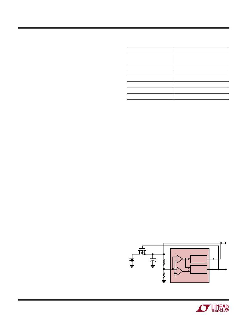
�The� LTC1558� enters� backup� mode� when� the� main� battery�
�voltage� drops.� As� shown� in� Figure� 1,� the� main� battery�
�voltage� is� scaled� down� by� an� external� resistor� divider� and�
�fed� to� the� LTC1558’s� backup� comparators.� These� com-�
�pare� the� scaled� voltage� with� an� internal� trimmed� V� REF�
�(1.272V),� switching� the� LTC1558� into� backup� mode�
�when� V� FB� drops� 7.5%� below� V� REF� .� Upon� entering� backup�
�mode,� the� BACKUP� pin� is� asserted� and� the� internal� boost�
�converter� turns� on.� The� BACKUP� signal� is� used� to� turn� off�
�the� external� P-channel� MOSFET,� isolating� the� main� bat-�
�tery� from� the� LTC1558� and� the� system� regulator’s� input.�
�The� LTC1558’s� boost� converter� will� charge� the� input�
�capacitor� C� IN� of� the� system� regulator� until� V� FB� rises�
�above� (V� REF� –� 7.5%).�
�TO� SYSTEM� REGULATOR� INPUT�
�Boost� Converter� Operation�
�The� LTC1558� uses� an� onboard� synchronous� boost� con-�
�MAIN�
�BATTERY�
�+�
�C� IN�
�R1�
�LTC1588�
�BOOST�
�CONVERTER�
�V� BAK�
�verter� with� a� fixed� peak� current� architecture� that� provides�
�a� simple� and� flexible� system� solution� while� eliminating� the�
�need� for� conventional� frequency� compensation.� The� boost�
�FB�
�R2�
�V� REF�
�BACKUP�
�LOGIC�
�BACKUP�
�1558� F01�
�converter’s� output,� set� by� the� external� divider� connected�
�to� the� FB� pin,� supports� the� main� system� regulator� during�
�8�
�Figure� 1.� Typical� LTC1558� Connection�
�相关PDF资料 |
PDF描述 |
|---|---|
| EEC49DREN-S13 | CONN EDGECARD 98POS .100 EXTEND |
| LTC1558CS-5#PBF | IC BACKUP BATT CNTRLR 5V 16-SOIC |
| EEC49DREH-S13 | CONN EDGECARD 98POS .100 EXTEND |
| LTC1559CGN-5#PBF | IC BACKUP BATT CNTRLR 5V 16-SSOP |
| RNM-3.312S | CONV DC/DC 1W 3.3VIN 12VOUT |
相关代理商/技术参数 |
参数描述 |
|---|---|
| LTC1558CGN-5 | 功能描述:IC BACKUP BATT CNTRLR 5V 16-SSOP RoHS:否 类别:集成电路 (IC) >> PMIC - 电池管理 系列:- 标准包装:2,000 系列:Impedance Track™ 功能:燃料,电量检测计/监控器 电池化学:锂离子(Li-Ion) 电源电压:2.4 V ~ 2.6 V 工作温度:-40°C ~ 85°C 安装类型:表面贴装 封装/外壳:20-TSSOP(0.173",4.40mm 宽) 供应商设备封装:20-TSSOP 包装:带卷 (TR) 产品目录页面:1020 (CN2011-ZH PDF) 配用:BQ27350EVM-ND - BQ27350EVM 其它名称:296-21665-2 |
| LTC1558CGN-5#PBF | 功能描述:IC BACKUP BATT CNTRLR 5V 16-SSOP RoHS:是 类别:集成电路 (IC) >> PMIC - 电池管理 系列:- 标准包装:1 系列:- 功能:充电管理 电池化学:锂离子(Li-Ion)、锂聚合物(Li-Pol) 电源电压:3.75 V ~ 6 V 工作温度:-40°C ~ 85°C 安装类型:表面贴装 封装/外壳:SC-74A,SOT-753 供应商设备封装:SOT-23-5 包装:剪切带 (CT) 产品目录页面:669 (CN2011-ZH PDF) 其它名称:MCP73831T-2ACI/OTCT |
| LTC1558CGN-5#TRPBF | 功能描述:IC BACKUP BATT CNTRLR 5V 16-SSOP RoHS:是 类别:集成电路 (IC) >> PMIC - 电池管理 系列:- 标准包装:1 系列:- 功能:充电管理 电池化学:锂离子(Li-Ion)、锂聚合物(Li-Pol) 电源电压:3.75 V ~ 6 V 工作温度:-40°C ~ 85°C 安装类型:表面贴装 封装/外壳:SC-74A,SOT-753 供应商设备封装:SOT-23-5 包装:剪切带 (CT) 产品目录页面:669 (CN2011-ZH PDF) 其它名称:MCP73831T-2ACI/OTCT |
| LTC1558CS-3.3 | 功能描述:IC BACKUP BATT CNTRLR3.3V 16SOIC RoHS:否 类别:集成电路 (IC) >> PMIC - 电池管理 系列:- 标准包装:61 系列:- 功能:电源管理 电池化学:锂离子(Li-Ion)、锂聚合物(Li-Pol) 电源电压:4.35 V ~ 5.5 V 工作温度:-40°C ~ 85°C 安装类型:表面贴装 封装/外壳:22-WFDFN 裸露焊盘 供应商设备封装:22-DFN(6x3)裸露焊盘 包装:管件 |
| LTC1558CS-3.3#PBF | 功能描述:IC BACKUP BATT CNTRLR3.3V 16SOIC RoHS:是 类别:集成电路 (IC) >> PMIC - 电池管理 系列:- 标准包装:1 系列:- 功能:充电管理 电池化学:锂离子(Li-Ion)、锂聚合物(Li-Pol) 电源电压:3.75 V ~ 6 V 工作温度:-40°C ~ 85°C 安装类型:表面贴装 封装/外壳:SC-74A,SOT-753 供应商设备封装:SOT-23-5 包装:剪切带 (CT) 产品目录页面:669 (CN2011-ZH PDF) 其它名称:MCP73831T-2ACI/OTCT |
发布紧急采购,3分钟左右您将得到回复。