- 您现在的位置:买卖IC网 > PDF目录1827 > LTC1558CS-3.3 (Linear Technology)IC BACKUP BATT CNTRLR3.3V 16SOIC PDF资料下载
参数资料
| 型号: | LTC1558CS-3.3 |
| 厂商: | Linear Technology |
| 文件页数: | 9/20页 |
| 文件大小: | 0K |
| 描述: | IC BACKUP BATT CNTRLR3.3V 16SOIC |
| 标准包装: | 50 |
| 功能: | 备份管理 |
| 电池化学: | 镍镉 |
| 电源电压: | 2.9 V ~ 3.46 V |
| 工作温度: | 0°C ~ 70°C |
| 安装类型: | 表面贴装 |
| 封装/外壳: | 16-SOIC(0.154",3.90mm 宽) |
| 供应商设备封装: | 16-SOIC |
| 包装: | 管件 |
�� �
�
�LTC1558-3.3/LTC1558-5�
�APPLICATIO� N� S� I� N� FOR� M� ATIO� N�
�Once� V� FB� rises� above� (V� REF� –� 7.5%),� the� LTC1558’s� boost�
�converter� deactivates� and� the� freshly� charged� input�
�capacitor� supplies� power� to� the� system� regulator.� The�
�cycle� repeats� again� when� the� input� capacitor’s� charge� is�
�drained� away� and� V� FB� again� drops� below� (V� REF� –� 7.5%).�
�The� BACKUP� pin� remains� asserted� until� the� main� battery�
�is� restored.� This� ensures� that� the� LTC1558� does� not� switch�
�in� and� out� of� backup� mode� unnecessarily.�
�The� LTC1558’s� boost� converter� minimizes� output� ripple�
�under� light� load� conditions� by� reducing� the� charge� trans-�
�ferred� for� the� first� two� consecutive� switch� cycles.� When�
�V� FB� falls� below� (V� REF� –� 7.5%),� the� boost� operation� starts�
�by� connecting� the� SW� pin� to� ground� through� an� internal�
�0.5� ?� N-channel� MOSFET� (N1� in� the� Block� Diagram).� The�
�current� through� the� external� 22� μ� H� inductor� rises� linearly�
�through� this� switch.�
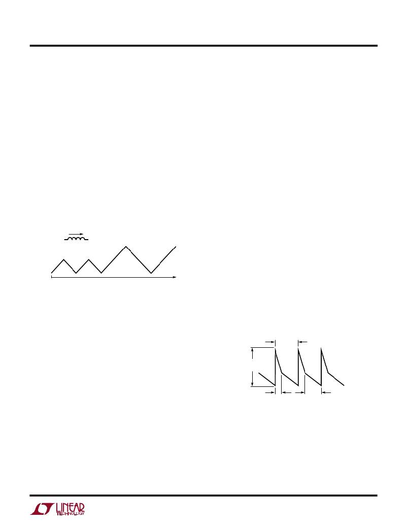
�330mA�
�and� doubles� the� internal� inductor� charging� current� limit� to�
�330mA� for� subsequent� cycles.� This� is� high� current� mode.�
�By� doubling� the� peak� inductor� current,� each� boost� cycle�
�effectively� carries� four� times� more� energy� compared� to�
�low� current� mode� (E� =� 1/2� ?� LI� 2� ),� doubling� the� available�
�output� power.� When� V� FB� exceeds� the� (V� REF� –� 7.5%)� boost�
�threshold,� the� LTC1558� stops� the� boost� converter� and�
�resets� the� internal� two� pulse� counter.� The� next� time� V� FB�
�falls� below� (V� REF� –� 7.5%),� the� boost� converter� restarts� in�
�low� current� mode� for� at� least� two� boost� cycles.� Moderate�
�or� changing� loads� will� cause� the� LTC1558� to� shift� between�
�the� two� peak� inductor� current� limits,� keeping� the� output� in�
�tight� regulation.� Near� its� maximum� load� capability,� the�
�LTC1558� will� stay� in� 330mA� high� current� mode� and� the�
�output� voltage� V� BAK� will� hover� around� the� user� pro-�
�grammed� value.�
�V� BAK� Capacitor� ESR�
�165mA�
�(PEAK)�
�(PEAK)�
�The� type� of� output� capacitor� and� the� user� programmed�
�V� BAK� value� will� affect� the� LTC1558’s� output� ripple� and�
�efficiency.� In� most� applications,� the� main� V� BAK� capacitor�
�is� primarily� determined� by� the� requirements� of� the� main�
�LIGHT� CURRENT� MODE�
�HEAVY� CURRENT� MODE�
�1558� F02�
�power� supply.� Such� a� capacitor� will� generally� meet� the�
�Figure� 2.� Inductor� Current� During� Switching�
�When� the� switch� current� reaches� an� internally� preset� level�
�of� 165mA,� the� boost� converter� connects� the� SW� pin� to� the�
�V� BAK� pin� through� an� internal� 2� ?� P-channel� MOSFET� (P1� in�
�the� Block� Diagram).� The� inductor� current� discharges�
�through� P1,� charging� up� the� capacitor� connected� exter-�
�nally� to� V� BAK� (C� IN� of� the� system� regulator,� Figure� 1).� The�
�inductor� current� falls� at� a� rate� proportional� to� the� differ-�
�ence� between� the� backup� cell� voltage� and� the� output�
�voltage� V� BAK� .� When� the� inductor� current� reaches� zero,�
�requirements� of� the� LTC1558.� In� unusual� circumstances�
�or� circuits� where� the� main� system� regulator’s� input� ca-�
�pacitor� is� located� some� distance� away� from� the� LTC1558,�
�a� local� output� capacitor� may� be� necessary.�
�1�
�BOOST�
�CYCLE�
�V� BAK�
�ESR� RIPPLE�
�indicating� all� of� its� energy� has� been� transferred� to� the�
�output� capacitor,� the� LTC1558� looks� at� the� FB� pin� voltage.�
�If� V� FB� has� increased� above� the� (V� REF� –� 7.5%)� threshold,�
�DISCHARGE�
�PERIOD�
�t� DISCH�
�CHARGE�
�PERIOD�
�t� CH�
�1588� F03�
�the� boost� converter� shuts� off� both� switches� and� waits� for�
�V� FB� to� drop� below� (V� REF� –� 7.5%)� again.�
�If� V� FB� is� still� less� than� (V� REF� –� 7.5%)� after� the� first� boost�
�cycle,� the� LTC1558� immediately� reconnects� SW� to� ground,�
�repeating� the� boost� cycle.� If� after� two� consecutive� pulses,�
�V� FB� is� still� not� above� the� boost� threshold� (V� REF� –� 7.5%),�
�the� LTC1558� decides� that� the� load� is� not� so� light� after� all,�
�Figure� 3.� V� BAK� Ripple�
�The� maximum� ripple� on� the� V� BAK� pin� is� equal� to� capacitor�
�ESR� voltage� drop� due� to� the� boost� converter’s� output�
�current� pulses.� The� ripple� frequency� and� output� duty� cycle�
�is� proportional� to� the� inductor� discharge� time.� Given� a�
�fixed� inductor� value� (22� μ� H)� and� a� known� peak� current�
�limit,� the� booster’s� discharge� time� in� each� boost� cycle� is�
�9�
�相关PDF资料 |
PDF描述 |
|---|---|
| LTC1559CS-5 | IC BACKUP BATT CNTRLR 5V 16-SOIC |
| LTC1574CS-3.3#TRPBF | IC REG BUCK INV 3.3V 16SOIC |
| LTC1622CMS8#PBF | IC REG CTRLR BUCK PWM CM 8-MSOP |
| LTC1624IS8#PBF | IC REG CTRLR BST FLYBK INV 8SOIC |
| LTC1625IGN#PBF | IC REG CTRLR BUCK PWM CM 16-SSOP |
相关代理商/技术参数 |
参数描述 |
|---|---|
| LTC1558CS-5 | 功能描述:IC BACKUP BATT CNTRLR 5V 16-SOIC RoHS:否 类别:集成电路 (IC) >> PMIC - 电池管理 系列:- 标准包装:2,000 系列:Impedance Track™ 功能:燃料,电量检测计/监控器 电池化学:锂离子(Li-Ion) 电源电压:2.4 V ~ 2.6 V 工作温度:-40°C ~ 85°C 安装类型:表面贴装 封装/外壳:20-TSSOP(0.173",4.40mm 宽) 供应商设备封装:20-TSSOP 包装:带卷 (TR) 产品目录页面:1020 (CN2011-ZH PDF) 配用:BQ27350EVM-ND - BQ27350EVM 其它名称:296-21665-2 |
| LTC1558CS-5#PBF | 功能描述:IC BACKUP BATT CNTRLR 5V 16-SOIC RoHS:是 类别:集成电路 (IC) >> PMIC - 电池管理 系列:- 标准包装:1 系列:- 功能:充电管理 电池化学:锂离子(Li-Ion)、锂聚合物(Li-Pol) 电源电压:3.75 V ~ 6 V 工作温度:-40°C ~ 85°C 安装类型:表面贴装 封装/外壳:SC-74A,SOT-753 供应商设备封装:SOT-23-5 包装:剪切带 (CT) 产品目录页面:669 (CN2011-ZH PDF) 其它名称:MCP73831T-2ACI/OTCT |
| LTC1558CS-5#TRPBF | 功能描述:IC BACKUP BATT CNTRLR 5V 16-SOIC RoHS:是 类别:集成电路 (IC) >> PMIC - 电池管理 系列:- 标准包装:1 系列:- 功能:充电管理 电池化学:锂离子(Li-Ion)、锂聚合物(Li-Pol) 电源电压:3.75 V ~ 6 V 工作温度:-40°C ~ 85°C 安装类型:表面贴装 封装/外壳:SC-74A,SOT-753 供应商设备封装:SOT-23-5 包装:剪切带 (CT) 产品目录页面:669 (CN2011-ZH PDF) 其它名称:MCP73831T-2ACI/OTCT |
| LTC1558CS8-3.3 | 功能描述:IC BACKUP BATT CNTRLR 3.3V 8SOIC RoHS:否 类别:集成电路 (IC) >> PMIC - 电池管理 系列:- 标准包装:2,000 系列:Impedance Track™ 功能:燃料,电量检测计/监控器 电池化学:锂离子(Li-Ion) 电源电压:2.4 V ~ 2.6 V 工作温度:-40°C ~ 85°C 安装类型:表面贴装 封装/外壳:20-TSSOP(0.173",4.40mm 宽) 供应商设备封装:20-TSSOP 包装:带卷 (TR) 产品目录页面:1020 (CN2011-ZH PDF) 配用:BQ27350EVM-ND - BQ27350EVM 其它名称:296-21665-2 |
| LTC1558CS8-3.3#PBF | 功能描述:IC BACKUP BATT CNTRLR 3.3V 8SOIC RoHS:是 类别:集成电路 (IC) >> PMIC - 电池管理 系列:- 标准包装:1 系列:- 功能:充电管理 电池化学:锂离子(Li-Ion)、锂聚合物(Li-Pol) 电源电压:3.75 V ~ 6 V 工作温度:-40°C ~ 85°C 安装类型:表面贴装 封装/外壳:SC-74A,SOT-753 供应商设备封装:SOT-23-5 包装:剪切带 (CT) 产品目录页面:669 (CN2011-ZH PDF) 其它名称:MCP73831T-2ACI/OTCT |
发布紧急采购,3分钟左右您将得到回复。