- 您现在的位置:买卖IC网 > PDF目录44988 > LTC1729CS8-8.4#TR (LINEAR TECHNOLOGY CORP) 1-CHANNEL POWER SUPPLY SUPPORT CKT, PDSO8 PDF资料下载
参数资料
| 型号: | LTC1729CS8-8.4#TR |
| 厂商: | LINEAR TECHNOLOGY CORP |
| 元件分类: | 电源管理 |
| 英文描述: | 1-CHANNEL POWER SUPPLY SUPPORT CKT, PDSO8 |
| 封装: | 0.150 INCH, PLASTIC, SO-8 |
| 文件页数: | 2/16页 |
| 文件大小: | 216K |
| 代理商: | LTC1729CS8-8.4#TR |
10
LTC1729 Series
Status Output Pin
The STATUS pin is designed to provide an indication that
the battery is charging. Once the current drops below the
C/10 threshold, the battery is close to being fully charged.
The LTC1729 turns off the hard pull-down once the
C/10 comparator is active for more than three seconds.
The 50
A soft pull down remains in effect until the 3-hour
time-out is completed or the input power is removed.
By using two different value pull-up resistors, a micropro-
cessor can detect three states from this pin (charging,
C/10 and stop charging). See Figure 7.
Second, if the battery is removed from the charger, the
VMAX signal is activated as mentioned in the Block Dia-
gram section. This causes the state machine to make the
VBAT > VMAX transition to the Pause state. The third way to
exit the charger “ON” state is with a VBAT < VMIN transition
to the Precondition state. The battery will need to drop
below 2.6V/cell to be less than VMIN. This is not a likely
scenario.
Once in the Pause state, there are two ways to proceed.
The first is to go to the No Bat state. This requires that the
VBAT remain greater than VMAX for more than one
second. From these conditions, the LTC1729 interprets
that a battery has been removed. If the voltage on the BAT
pin stays less than VMAX for more than one second, then
the state machine returns to the Charge state (Precondi-
tion and charger “ON”). This is interpreted as a momentary
open caused by the battery pack protection circuitry or
loose contact.
The Done state can only proceed to the No Bat state. From
outside the LTC1729 this transition is undetectable. The
requirement for this transition is for the BAT pin voltage to
exceed VMAX for more than one second. The IC now
assumes that the battery has been removed.
From the No Bat state, there is only one possible transition.
The No Bat state can move to the Charge state if the voltage
on the BAT pin remains less than VMAX for one second. The
LTC1729 will now work on the assumption that a new
battery has been installed.
Although the Precondition and Charger “ON” both reside
in the Charge state, there are differences between these
states. The main purpose of the Precondition state is to
slowly bring a heavily discharged battery up to a minimum
level before full charge current begins. The Precondition
state uses a 12mA current source to trickle charge the
battery with a 1-hour time-out transition to the Done state.
The Charger “ON” state enables the external charger and
the time-out is increased to three hours. For the entire
time in the Precondition state, the STATUS pin uses a hard
pull-down. In the Charger “ON” state the STATUS pin uses
two types of pull-down: hard pull-down and soft 50
A
pull-down.
APPLICATIO S I FOR ATIO
WU
UU
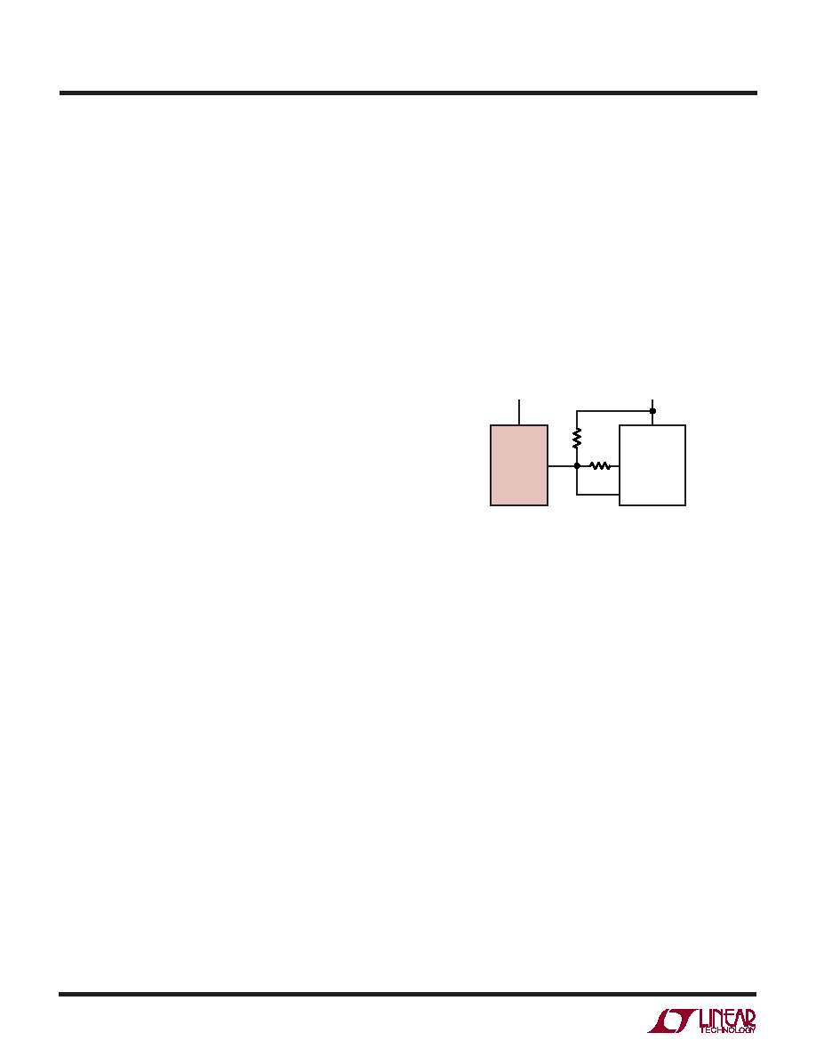
3k
200k
STATUS
1729 F07
VCC
LTC1729
VIN
VDD
OUT
PROCESSOR
IN
6
8
Figure 7. Microprocessor Interface
When the LTC1729 is in charge mode, the STATUS pin is
pulled down by an internal N-channel MOSFET. To detect
this mode, force the digital output pin, OUT, high and
measure the voltage at the STATUS pin. The N-channel
MOSFET will pull the pin low even with a 3k pull-up resis-
tor. Once the charge current drops to 10% of the full-scale
current (C/10), the N-channel MOSFET is turned off and a
50
A current source is connected to the STATUS pin. The
IN pin will then be pulled high by the 3k pull-up. By forcing
the OUT pin into a high impedance state, the current
source will pull the pin low through the 200k resistor.
When the internal timer has expired, the STATUS pin will
change to high impedance state and the 200k resistor will
then pull the pin high to indicate the charging has stopped.
Terminate at C/10 Current
Charging can also be terminated using C/10 detection
before the 3-hour time-out. By connecting the low side of
the NTC thermistor to the STATUS pin instead of ground,
相关PDF资料 |
PDF描述 |
|---|---|
| LTC1772BIS6#PBF | 1 A SWITCHING CONTROLLER, 650 kHz SWITCHING FREQ-MAX, PDSO6 |
| LTC1871EMS#PBF-1 | SWITCHING CONTROLLER, 1000 kHz SWITCHING FREQ-MAX, PDSO10 |
| LTC1871EMS#TR-1 | SWITCHING CONTROLLER, 1000 kHz SWITCHING FREQ-MAX, PDSO10 |
| LTC1871IMS#TRPBF-1 | SWITCHING CONTROLLER, 1000 kHz SWITCHING FREQ-MAX, PDSO10 |
| LTC1871HMS#TR | 0.05 A SWITCHING CONTROLLER, 1000 kHz SWITCHING FREQ-MAX, PDSO10 |
相关代理商/技术参数 |
参数描述 |
|---|---|
| LTC1730EGN-4 | 功能描述:IC BATT PULSE CHRGR LI-ION16SSOP RoHS:否 类别:集成电路 (IC) >> PMIC - 电池管理 系列:- 标准包装:61 系列:- 功能:电源管理 电池化学:锂离子(Li-Ion)、锂聚合物(Li-Pol) 电源电压:4.35 V ~ 5.5 V 工作温度:-40°C ~ 85°C 安装类型:表面贴装 封装/外壳:22-WFDFN 裸露焊盘 供应商设备封装:22-DFN(6x3)裸露焊盘 包装:管件 |
| LTC1730EGN-4#PBF | 功能描述:IC BATT PULSE CHRGR LI-ION16SSOP RoHS:是 类别:集成电路 (IC) >> PMIC - 电池管理 系列:- 标准包装:61 系列:- 功能:电源管理 电池化学:锂离子(Li-Ion)、锂聚合物(Li-Pol) 电源电压:4.35 V ~ 5.5 V 工作温度:-40°C ~ 85°C 安装类型:表面贴装 封装/外壳:22-WFDFN 裸露焊盘 供应商设备封装:22-DFN(6x3)裸露焊盘 包装:管件 |
| LTC1730EGN-4#TR | 功能描述:IC BATT PULSE CHRGR LI-ION16SSOP RoHS:否 类别:集成电路 (IC) >> PMIC - 电池管理 系列:- 标准包装:61 系列:- 功能:电源管理 电池化学:锂离子(Li-Ion)、锂聚合物(Li-Pol) 电源电压:4.35 V ~ 5.5 V 工作温度:-40°C ~ 85°C 安装类型:表面贴装 封装/外壳:22-WFDFN 裸露焊盘 供应商设备封装:22-DFN(6x3)裸露焊盘 包装:管件 |
| LTC1730EGN-4#TRPBF | 功能描述:IC BATT PULSE CHRGR LI-ION16SSOP RoHS:是 类别:集成电路 (IC) >> PMIC - 电池管理 系列:- 标准包装:61 系列:- 功能:电源管理 电池化学:锂离子(Li-Ion)、锂聚合物(Li-Pol) 电源电压:4.35 V ~ 5.5 V 工作温度:-40°C ~ 85°C 安装类型:表面贴装 封装/外壳:22-WFDFN 裸露焊盘 供应商设备封装:22-DFN(6x3)裸露焊盘 包装:管件 |
| LTC1730ES8-4.2 | 功能描述:IC BATT PULSE CHRGR LI-ION 8SOIC RoHS:否 类别:集成电路 (IC) >> PMIC - 电池管理 系列:- 标准包装:61 系列:- 功能:电源管理 电池化学:锂离子(Li-Ion)、锂聚合物(Li-Pol) 电源电压:4.35 V ~ 5.5 V 工作温度:-40°C ~ 85°C 安装类型:表面贴装 封装/外壳:22-WFDFN 裸露焊盘 供应商设备封装:22-DFN(6x3)裸露焊盘 包装:管件 |
发布紧急采购,3分钟左右您将得到回复。