- 您现在的位置:买卖IC网 > PDF目录15288 > LTC1735IGN#TRPBF (Linear Technology)IC REG CTRLR BUCK PWM CM 16-SSOP PDF资料下载
参数资料
| 型号: | LTC1735IGN#TRPBF |
| 厂商: | Linear Technology |
| 文件页数: | 12/32页 |
| 文件大小: | 0K |
| 描述: | IC REG CTRLR BUCK PWM CM 16-SSOP |
| 标准包装: | 2,500 |
| PWM 型: | 电流模式 |
| 输出数: | 1 |
| 频率 - 最大: | 335kHz |
| 占空比: | 99.4% |
| 电源电压: | 4 V ~ 30 V |
| 降压: | 是 |
| 升压: | 无 |
| 回扫: | 无 |
| 反相: | 无 |
| 倍增器: | 无 |
| 除法器: | 无 |
| Cuk: | 无 |
| 隔离: | 无 |
| 工作温度: | -40°C ~ 85°C |
| 封装/外壳: | 16-SSOP(0.154",3.90mm 宽) |
| 包装: | 带卷 (TR) |
第1页第2页第3页第4页第5页第6页第7页第8页第9页第10页第11页当前第12页第13页第14页第15页第16页第17页第18页第19页第20页第21页第22页第23页第24页第25页第26页第27页第28页第29页第30页第31页第32页
�� �
�
�LTC1735�
�APPLICATIO� S� I� FOR� ATIO�
�The� internal� oscillator� runs� at� its� nominal� frequency� (f� O� )�
�when� the� FCB� pin� is� pulled� high� to� INTV� CC� or� connected� to�
�ground.� Clocking� the� FCB� pin� above� and� below� 0.8V� will�
�cause� the� internal� oscillator� to� injection� lock� to� an� external�
�clock� signal� applied� to� the� FCB� pin� with� a� frequency�
�between� 0.9f� O� and� 1.3f� O� .� The� clock� high� level� must� exceed�
�1.3V� for� at� least� 0.3� μ� s� and� the� clock� low� level� must� be� less�
�than� 0.3V� for� at� least� 0.3� μ� s.� The� top� MOSFET� turn-on� will�
�synchronize� with� the� rising� edge� of� the� clock.�
�Attempting� to� synchronize� to� too� high� an� external� fre-�
�of� smaller� inductor� and� capacitor� values.� So� why� would�
�anyone� ever� choose� to� operate� at� lower� frequencies� with�
�larger� components?� The� answer� is� efficiency.� A� higher�
�frequency� generally� results� in� lower� efficiency� because� of�
�MOSFET� gate� charge� losses.� In� addition� to� this� basic� trade�
�off,� the� effect� of� inductor� value� on� ripple� current� and� low�
�current� operation� must� also� be� considered.�
�The� inductor� value� has� a� direct� effect� on� ripple� current.� The�
�inductor� ripple� current� ?� I� L� decreases� with� higher� induc-�
�tance� or� frequency� and� increases� with� higher� V� IN� or� V� OUT� :�
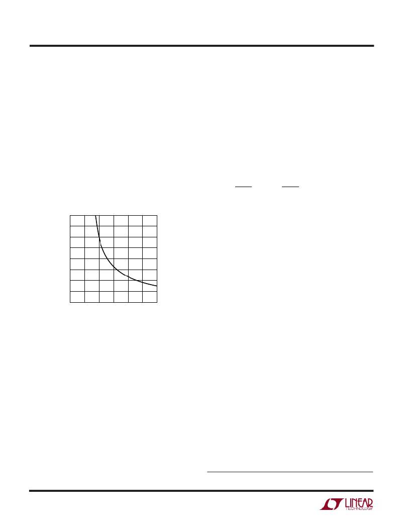
�quency� (above� 1.3f� O� )� can� result� in� inadequate� slope� com-�
�pensation� and� possible� loop� instability.� If� this� condition�
�exists� simply� lower� the� value� of� C� OSC� so� f� EXT� =� f� O� according�
�to� Figure� 2.�
�?� I� L� =�
�1�
�(� f� )(� L� )�
�?� V� ?�
�V� OUT� ?� 1� –� OUT� ?�
�?� V� IN� ?�
�100.0�
�87.5�
�75.0�
�62.5�
�50.0�
�37.5�
�25.0�
�Accepting� larger� values� of� ?� I� L� allows� the� use� of� low�
�inductances,� but� results� in� higher� output� voltage� ripple�
�and� greater� core� losses.� A� reasonable� starting� point� for�
�setting� ripple� current� is� ?� I� L� =� 0.3� to� 0.4(I� MAX� ).� Remember,�
�the� maximum� ?� I� L� occurs� at� the� maximum� input� voltage.�
�The� inductor� value� also� has� an� effect� on� low� current�
�operation.� The� transition� to� low� current� operation� begins�
�when� the� inductor� current� reaches� zero� while� the� bottom�
�12.5�
�0�
�0�
�100� 200� 300� 400� 500�
�OPERATING� FREQUENCY� (kHZ)�
�600�
�MOSFET� is� on.� Burst� Mode� operation� begins� when� the�
�average� inductor� current� required� results� in� a� peak� current�
�below� 25%� of� the� current� limit� determined� by� R� SENSE� .�
�Lower� inductor� values� (higher� ?� I� L� )� will� cause� this� to� occur�
�1735� F02�
�Figure� 2.� Timing� Capacitor� Value�
�When� synchronized� to� an� external� clock,� Burst� Mode�
�operation� is� disabled� but� the� inductor� current� is� not�
�allowed� to� reverse.� The� 25%� minimum� inductor� current�
�clamp� present� in� Burst� Mode� operation� is� removed,�
�providing� constant� frequency� discontinuous� operation�
�over� the� widest� possible� output� current� range.� In� this�
�mode� the� synchronous� MOSFET� is� forced� on� once� every�
�10� clock� cycles� to� recharge� the� bootstrap� capacitor.� This�
�minimizes� audible� noise� while� maintaining� reasonably�
�high� efficiency.�
�Inductor� Value� Calculation�
�The� operating� frequency� and� inductor� selection� are� inter-�
�related� in� that� higher� operating� frequencies� allow� the� use�
�at� higher� load� currents,� which� can� cause� a� dip� in� efficiency�
�in� the� upper� range� of� low� current� operation.� In� Burst� Mode�
�operation,� lower� inductance� values� will� cause� the� burst�
�frequency� to� decrease.�
�Inductor� Core� Selection�
�Once� the� value� for� L� is� known,� the� type� of� inductor� must� be�
�selected.� High� efficiency� converters� generally� cannot� af-�
�ford� the� core� loss� found� in� low� cost� powdered� iron� cores,�
�forcing� the� use� of� more� expensive� ferrite,� molypermalloy�
�or� Kool� M� μ� ?� cores.� Actual� core� loss� is� independent� of�
�core� size� for� a� fixed� inductor� value,� but� it� is� very� dependent�
�on� inductance� selected.� As� inductance� increases,� core�
�losses� decrease.� Unfortunately,� increased� inductance� re-�
�quires� more� turns� of� wire� and� therefore� copper� losses� will�
�increase.�
�Kool� M� μ� is� a� registered� trademark� of� Magnetics,� Inc.�
�1735fc�
�12�
�相关PDF资料 |
PDF描述 |
|---|---|
| RLB9012-331KL | INDUCTOR HI CURRENT RADIAL 330UH |
| LTC3736EGN#TRPBF | IC REG CTRLR BUCK PWM CM 24-SSOP |
| GBM43DTMH | CONN EDGECARD 86POS R/A .156 SLD |
| LTC3736EGN#TR | IC REG CTRLR BUCK PWM CM 24-SSOP |
| LT3844IFE#PBF | IC REG CTRLR BST INV PWM 16TSSOP |
相关代理商/技术参数 |
参数描述 |
|---|---|
| LTC1735IS | 功能描述:IC REG CTRLR BUCK PWM CM 16-SOIC RoHS:否 类别:集成电路 (IC) >> PMIC - 稳压器 - DC DC 切换控制器 系列:- 标准包装:2,500 系列:- PWM 型:电流模式 输出数:1 频率 - 最大:500kHz 占空比:96% 电源电压:4 V ~ 36 V 降压:无 升压:是 回扫:无 反相:无 倍增器:无 除法器:无 Cuk:无 隔离:无 工作温度:-40°C ~ 125°C 封装/外壳:24-WQFN 裸露焊盘 包装:带卷 (TR) |
| LTC1735IS#PBF | 功能描述:IC REG CTRLR BUCK PWM CM 16-SOIC RoHS:是 类别:集成电路 (IC) >> PMIC - 稳压器 - DC DC 切换控制器 系列:- 特色产品:LM3753/54 Scalable 2-Phase Synchronous Buck Controllers 标准包装:1 系列:PowerWise® PWM 型:电压模式 输出数:1 频率 - 最大:1MHz 占空比:81% 电源电压:4.5 V ~ 18 V 降压:是 升压:无 回扫:无 反相:无 倍增器:无 除法器:无 Cuk:无 隔离:无 工作温度:-5°C ~ 125°C 封装/外壳:32-WFQFN 裸露焊盘 包装:Digi-Reel® 产品目录页面:1303 (CN2011-ZH PDF) 其它名称:LM3754SQDKR |
| LTC1735IS#TR | 功能描述:IC REG CTRLR BUCK PWM CM 16-SOIC RoHS:否 类别:集成电路 (IC) >> PMIC - 稳压器 - DC DC 切换控制器 系列:- 标准包装:2,500 系列:- PWM 型:电流模式 输出数:1 频率 - 最大:500kHz 占空比:96% 电源电压:4 V ~ 36 V 降压:无 升压:是 回扫:无 反相:无 倍增器:无 除法器:无 Cuk:无 隔离:无 工作温度:-40°C ~ 125°C 封装/外壳:24-WQFN 裸露焊盘 包装:带卷 (TR) |
| LTC1735IS#TRPBF | 功能描述:IC REG CTRLR BUCK PWM CM 16-SOIC RoHS:是 类别:集成电路 (IC) >> PMIC - 稳压器 - DC DC 切换控制器 系列:- 标准包装:2,500 系列:- PWM 型:电流模式 输出数:1 频率 - 最大:500kHz 占空比:96% 电源电压:4 V ~ 36 V 降压:无 升压:是 回扫:无 反相:无 倍增器:无 除法器:无 Cuk:无 隔离:无 工作温度:-40°C ~ 125°C 封装/外壳:24-WQFN 裸露焊盘 包装:带卷 (TR) |
| LTC1735IS-1 | 功能描述:IC REG CTRLR BUCK PWM CM 16-SOIC RoHS:否 类别:集成电路 (IC) >> PMIC - 稳压器 - DC DC 切换控制器 系列:- 标准包装:2,500 系列:- PWM 型:电流模式 输出数:1 频率 - 最大:500kHz 占空比:96% 电源电压:4 V ~ 36 V 降压:无 升压:是 回扫:无 反相:无 倍增器:无 除法器:无 Cuk:无 隔离:无 工作温度:-40°C ~ 125°C 封装/外壳:24-WQFN 裸露焊盘 包装:带卷 (TR) |
发布紧急采购,3分钟左右您将得到回复。