- 您现在的位置:买卖IC网 > PDF目录11772 > LTC1756EGN#TR (Linear Technology)IC SMART CARD INTERFACE 16SSOP PDF资料下载
参数资料
| 型号: | LTC1756EGN#TR |
| 厂商: | Linear Technology |
| 文件页数: | 6/16页 |
| 文件大小: | 0K |
| 描述: | IC SMART CARD INTERFACE 16SSOP |
| 标准包装: | 2,500 |
| 应用: | 智能卡 |
| 电源电压: | 2.7 V ~ 6 V |
| 封装/外壳: | 16-SSOP(0.154",3.90mm 宽) |
| 供应商设备封装: | 16-SSOP |
| 包装: | 带卷 (TR) |
| 安装类型: | 表面贴装 |
14
LTC1755/LTC1756
APPLICATIO S I FOR ATIO
WU
UU
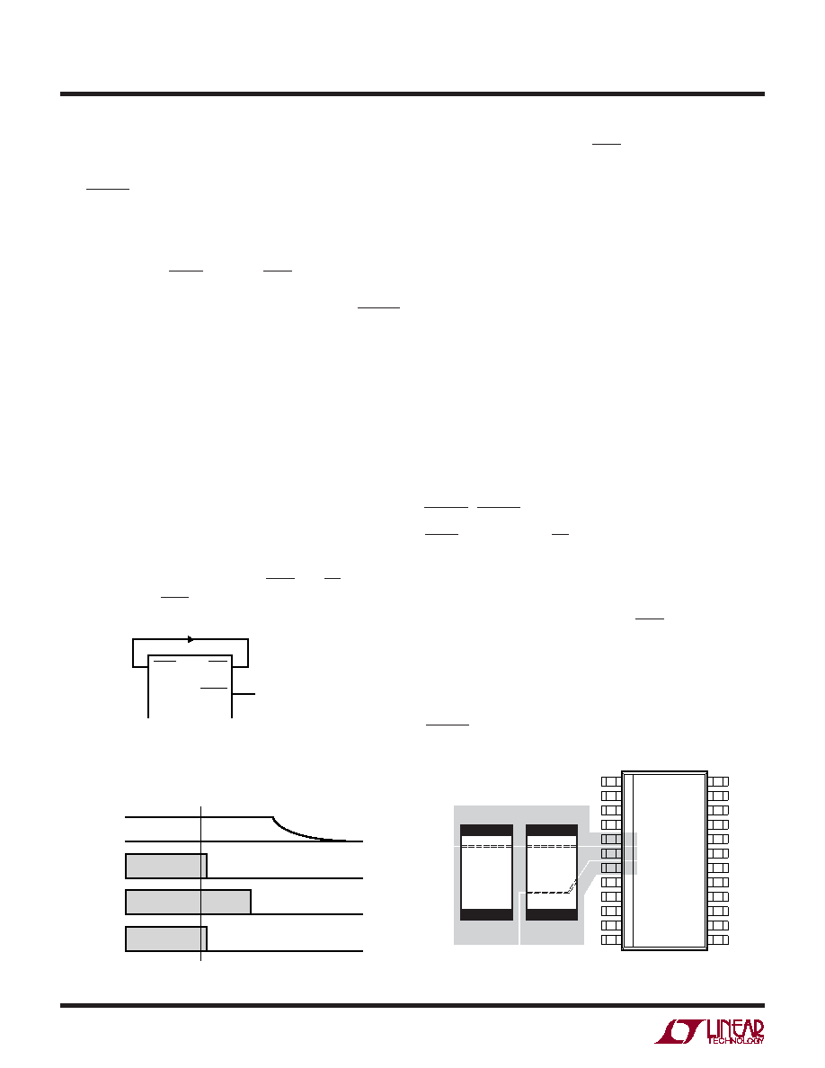
Figure 7. Deactivation Sequence
VCC
1755 F07
RST
CLK
I/O
AUX2
AUX1
RST = RIN
DEACTIVATION DIRECTIVE
CLK = CIN
I/O = DATA
GND
VIN
VCC
17556 F08
Figure 8. Optimum Bypass Capacitor Placement
Overtemperature Fault Protection
An overtemperature circuit disables the chip and activates
the ALARM pin if the IC’s junction temperature exceeds
150
°C.
Self-Start Mode
By connecting the CARD pin to the PWR pin, the LTC1755/
LTC1756 can be made to start up automatically when a
Smart Card is detected (Figure 6). In this mode, the READY
pin becomes an interrupt signal indicating to the micro-
controller that a Smart Card is present and that VCC, the
charge pump voltage, is at its final value. The Smart Card
remains powered as long as it is detected by the PRES pin.
When the Smart Card is removed the LTC1755/LTC1756
will automatically be deactivated by the fault detection
circuitry.
Deactivation Sequence
For maximum flexibility the Smart Card can be deactivated
either manually or automatically. In manual mode the de-
activation is controlled by explicitly manipulating the
LTC1755/LTC1756 input and control pins (DATA, AUX1IN,
AUX2IN, RIN and CIN followed by PWR and CS). In auto-
matic mode the PWR pin is used to perform the built-in
Figure 6. Self-Start Mode
CARD
TO
MICROCONTROLLER
PWR
READY
1755 F06
deactivation sequence. Once PWR is brought high the built-
in deactivation sequence occurs as shown in Figure 7.
In the event of a fault, the LTC1755/LTC1756 automatically
implement the built-in deactivation sequence.
PC Board Layout
For best performance, the VIN and VCC capacitors should
be placed as close to the LTC1755/LTC1756 as possible.
This will help reduce ringing due to inductance on the VIN
and VCC pins that could cause problems with the LTC1755/
LTC1756 control circuitry or Smart Card. Figure 8 illus-
trates a possible layout technique using only a single layer
of the PC board.
State Definitions
IDLE/DEACTIVATION
VCC, RST, CLK, I/O AUX2, AUX1 = L
READY, ALARM, DATA, AUX2IN, AUX1IN = Z
CARD = PRES
⊕ NC/NO
Once the LTC1755/LTC1756 enter the Idle/Deactivation
state the deactivation sequence begins. The deactivation
sequence will continue until VCC is discharged to approxi-
mately 1V. An activation command (PWR = 0V) will only be
acknowledged once this occurs.
ALARM/DEACTIVATION
Same as Idle/Deactivation except:
ALARM = L
相关PDF资料 |
PDF描述 |
|---|---|
| D38999/26WE26PB | CONN PLUG 26POS STRAIGHT W/PINS |
| V150B5H150BF2 | CONVERTER MOD DC/DC 5V 150W |
| PIC16LF722-I/SS | IC PIC MCU FLASH 3.5KB 28-SSOP |
| LTC1756EGN | IC SMART CARD 16-SSOP |
| V150C12H150BF2 | CONVERTER MOD DC/DC 12V 150W |
相关代理商/技术参数 |
参数描述 |
|---|---|
| LTC1757A-1EMS8 | 功能描述:IC CTRLR RF POWER SINGLE 8MSOP RoHS:否 类别:RF/IF 和 RFID >> RF 电源控制器 IC 系列:- 标准包装:3,000 系列:- RF 型:GSM 频率:450MHz ~ 2GHz 特点:四频带 封装/外壳:8-VFBGA 供应商设备封装:8-MicroSMD(1.51x1.51) 包装:带卷 (TR) 其它名称:LMV243BLX |
| LTC1757A-1EMS8#PBF | 功能描述:IC CTRLR RF POWER SINGLE 8MSOP RoHS:是 类别:RF/IF 和 RFID >> RF 电源控制器 IC 系列:- 标准包装:3,000 系列:- RF 型:GSM 频率:450MHz ~ 2GHz 特点:四频带 封装/外壳:8-VFBGA 供应商设备封装:8-MicroSMD(1.51x1.51) 包装:带卷 (TR) 其它名称:LMV243BLX |
| LTC1757A-1EMS8#TR | 功能描述:IC CTRLR RF POWER SINGLE 8MSOP RoHS:否 类别:RF/IF 和 RFID >> RF 电源控制器 IC 系列:- 标准包装:3,000 系列:- RF 型:GSM 频率:450MHz ~ 2GHz 特点:四频带 封装/外壳:8-VFBGA 供应商设备封装:8-MicroSMD(1.51x1.51) 包装:带卷 (TR) 其它名称:LMV243BLX |
| LTC1757A-1EMS8#TRPBF | 功能描述:IC CTRLR RF POWER SINGLE 8MSOP RoHS:是 类别:RF/IF 和 RFID >> RF 电源控制器 IC 系列:- 标准包装:3,000 系列:- RF 型:GSM 频率:450MHz ~ 2GHz 特点:四频带 封装/外壳:8-VFBGA 供应商设备封装:8-MicroSMD(1.51x1.51) 包装:带卷 (TR) 其它名称:LMV243BLX |
| LTC1757A-2EMS | 功能描述:IC CTRLR RF POWER DUAL 10MSOP RoHS:否 类别:RF/IF 和 RFID >> RF 电源控制器 IC 系列:- 标准包装:3,000 系列:- RF 型:GSM 频率:450MHz ~ 2GHz 特点:四频带 封装/外壳:8-VFBGA 供应商设备封装:8-MicroSMD(1.51x1.51) 包装:带卷 (TR) 其它名称:LMV243BLX |
发布紧急采购,3分钟左右您将得到回复。