- 您现在的位置:买卖IC网 > PDF目录1828 > LTC1911EMS8-1.5#TR (Linear Technology)IC REG BUCK 1.5V 0.25A 8MSOP PDF资料下载
参数资料
| 型号: | LTC1911EMS8-1.5#TR |
| 厂商: | Linear Technology |
| 文件页数: | 7/12页 |
| 文件大小: | 0K |
| 描述: | IC REG BUCK 1.5V 0.25A 8MSOP |
| 标准包装: | 2,500 |
| 类型: | 降压(降压) |
| 输出类型: | 固定 |
| 输出数: | 1 |
| 输出电压: | 1.5V |
| 输入电压: | 2.7 V ~ 5.5 V |
| PWM 型: | Burst Mode? |
| 频率 - 开关: | 1.5MHz |
| 电流 - 输出: | 250mA |
| 同步整流器: | 无 |
| 工作温度: | -40°C ~ 85°C |
| 安装类型: | 表面贴装 |
| 封装/外壳: | 8-TSSOP,8-MSOP(0.118",3.00mm 宽) |
| 包装: | 带卷 (TR) |
| 供应商设备封装: | 8-MSOP |
| 其它名称: | LTC1911EMS8-1.5TR LTC1911EMS81.5TR |
�� �
�
�LTC1911-1.5/LTC1911-1.8�
�APPLICATIO� S� I� FOR� ATIO�
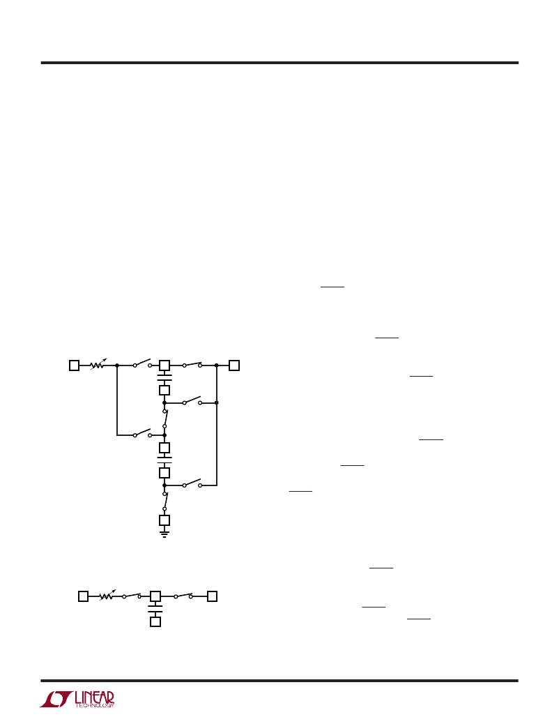
�transferred� to� the� parallel� combination� of� C1� and� C2� is�
�transferred� to� the� V� OUT� .� In� this� manner,� charge� is� again�
�transferred� from� the� flying� capacitors� to� the� output� on�
�both� phases� of� the� clock.� As� in� 2-to-1� mode,� charge�
�current� is� sourced� from� GND� on� phase� two� of� the� clock�
�resulting� in� increased� power� efficiency.� I� OUT� in� 3-to-2�
�mode� equals� approximately� (3/2)I� IN� .�
�In� 1-to-1� mode� (see� Figure� 1c),� switch� S1� is� always� closed�
�connecting� the� top� plate� of� C1� to� V� OUT� .� Switch� S2� remains�
�closed� for� almost� the� entire� clock� period,� opening� only�
�briefly� at� the� end� of� clock� phase� one.� In� this� manner,� V� OUT�
�is� connected� to� V� IN� through� R� A� .� The� value� of� R� A� is� set� by�
�the� regulator� control� loop� which� determines� the� amount� of�
�current� transferred� to� V� OUT� during� the� on� period� of� S2.� The�
�LTC1911� acts� much� like� a� linear� regulator� in� this� mode.�
�Since� all� of� the� V� OUT� current� is� sourced� from� V� IN� ,� the�
�efficiency� in� 1-to-1� mode� is� approximately� equal� to� that� of�
�a� linear� regulator.�
�Mode� Selection�
�The� optimal� step-down� conversion� mode� is� chosen� based�
�on� V� IN� and� output� load� conditions.� Two� internal� compara-�
�tors� are� used� to� select� the� default� step-down� mode� based�
�on� the� input� voltage.� Each� comparator� has� an� adjustable�
�offset� built� in� that� increases� (decreases)� in� proportion� to�
�the� increasing� (decreasing)� output� load� current.� In� this�
�manner,� the� mode� switch� point� is� optimized� to� provide�
�peak� efficiency� over� all� supply� and� load� conditions.� Each�
�comparator� also� has� built-in� hysteresis� of� about� 300mV� to�
�ensure� that� the� LTC1911� does� not� oscillate� between� modes�
�when� a� transition� point� is� reached.�
�Soft-Start/Shutdown� Operation�
�The� SS/SHDN� pin� is� used� to� implement� both� low� current�
�shutdown� and� soft-start.� The� soft-start� feature� limits�
�inrush� currents� when� the� regulator� is� initially� powered� up�
�or� taken� out� of� shutdown.� Forcing� a� voltage� lower� than�
�R� A�
�S5�
�φ� 1�
�C1� +�
�S1�
�φ� 2�
�0.6V� (typ)� on� the� SS/SHDN� pin� will� put� the� LTC1911� into�
�shutdown� mode.� Shutdown� mode� disables� all� control�
�V� IN�
�C1�
�C1� –�
�S4�
�φ� 1�
�V� OUT�
�circuitry� and� forces� V� OUT� into� a� high� impedance� state.� A�
�2� μ� A� pull-up� current� on� the� SS/SHDN� pin� will� force� the� part�
�into� active� mode� if� the� pin� is� left� floating� or� is� driven� with�
�S7�
�φ� 1�
�S2�
�φ� 2�
�C2� +�
�an� open-drain� output� that� is� in� a� high� impedance� state.� If�
�the� pin� is� not� driven� with� an� open-drain� device,� it� must� be�
�forced� to� a� logic� high� voltage� of� 2.2V� (min)� to� ensure�
�proper� V� OUT� regulation.� The� SS/SHDN� pin� should� not� be�
�C2�
�C2� –�
�S6�
�φ� 1�
�driven� to� a� voltage� higher� than� V� IN� .� To� implement� soft-�
�start,� the� SS/SHDN� pin� must� be� driven� with� an� open-drain�
�1911� F01b�
�S3�
�φ� 2�
�GND�
�Figure� 1b.� Step-Down� Charge� Transfer� in� 3-to-2� Mode�
�device� and� a� capacitor� must� be� connected� from� the� SS/�
�SHDN� pin� to� GND.� Once� the� open-drain� device� is� turned�
�off,� the� 2� μ� A� pull-up� current� will� begin� charging� the� external�
�soft-start� capacitor� and� force� the� voltage� on� the� pin� to�
�ramp� towards� V� IN� .� As� soon� as� the� shutdown� threshold� is�
�reached� (0.6V� typ),� the� internal� reference� voltage� that�
�controls� the� V� OUT� regulation� point� will� follow� the� ramp�
�voltage� on� the� SS/SHDN� pin� (minus� a� 0.6V� offset� to�
�V� IN�
�R� A�
�S2�
�C1� +�
�S1�
�V� OUT�
�account� for� the� shutdown� threshold)� until� the� reference�
�reaches� its� final� band� gap� voltage.� This� occurs� when� the�
�C1�
�voltage� on� the� SS/SHDN� pin� reaches� approximately� 1.9V.�
�C1� –�
�1911� F01c�
�Since� the� ramp� rate� on� the� SS/SHDN� pin� controls� the� ramp�
�rate� on� V� OUT� ,� the� average� inrush� current� can� be� controlled�
�Figure� 1c.� Step-Down� Charge� Transfer� in� 1-to-1� Mode�
�through� the� selection� of� C� SS� and� C� OUT� .� For� example,� a�
�1911f�
�7�
�相关PDF资料 |
PDF描述 |
|---|---|
| LTC1922EG-1#PBF | IC REG CTRLR ISO PWM 20-SSOP |
| LTC1928ES6-5#TRPBF | IC REG SWITCHED CAP DBL SOT23-6 |
| LTC1929IG-PG#TR | IC REG CTRLR BUCK PWM CM 28-SSOP |
| LTC1960CG#TR | IC BATT CHRGR/SELECTR DUAL36SSOP |
| LTC1980EGN#TRPBF | IC PWM BATT CHARGER/CONV 24-SSOP |
相关代理商/技术参数 |
参数描述 |
|---|---|
| LTC1920BCSW | 制造商:Linear Technology 功能描述: |
| LTC1921CMS8 | 功能描述:IC DUAL PWR SUPPLY MONITOR 8MSOP RoHS:否 类别:集成电路 (IC) >> PMIC - 电源控制器,监视器 系列:- 产品培训模块:Lead (SnPb) Finish for COTS Obsolescence Mitigation Program 标准包装:2,500 系列:- 应用:多相控制器 输入电压:- 电源电压:9 V ~ 14 V 电流 - 电源:- 工作温度:-40°C ~ 85°C 安装类型:表面贴装 封装/外壳:40-WFQFN 裸露焊盘 供应商设备封装:40-TQFN-EP(5x5) 包装:带卷 (TR) |
| LTC1921CMS8#PBF | 功能描述:IC DUAL PWR SUPPLY MONITOR 8MSOP RoHS:是 类别:集成电路 (IC) >> PMIC - 电源控制器,监视器 系列:- 产品培训模块:Lead (SnPb) Finish for COTS Obsolescence Mitigation Program 标准包装:2,500 系列:- 应用:多相控制器 输入电压:- 电源电压:9 V ~ 14 V 电流 - 电源:- 工作温度:-40°C ~ 85°C 安装类型:表面贴装 封装/外壳:40-WFQFN 裸露焊盘 供应商设备封装:40-TQFN-EP(5x5) 包装:带卷 (TR) |
| LTC1921CMS8#TR | 功能描述:IC DUAL PWR SUPPLY MONITOR 8MSOP RoHS:否 类别:集成电路 (IC) >> PMIC - 电源控制器,监视器 系列:- 产品培训模块:Lead (SnPb) Finish for COTS Obsolescence Mitigation Program 标准包装:2,500 系列:- 应用:多相控制器 输入电压:- 电源电压:9 V ~ 14 V 电流 - 电源:- 工作温度:-40°C ~ 85°C 安装类型:表面贴装 封装/外壳:40-WFQFN 裸露焊盘 供应商设备封装:40-TQFN-EP(5x5) 包装:带卷 (TR) |
| LTC1921CMS8#TRPBF | 功能描述:IC DUAL PWR SUPPLY MONITOR 8MSOP RoHS:是 类别:集成电路 (IC) >> PMIC - 电源控制器,监视器 系列:- 产品培训模块:Lead (SnPb) Finish for COTS Obsolescence Mitigation Program 标准包装:2,500 系列:- 应用:多相控制器 输入电压:- 电源电压:9 V ~ 14 V 电流 - 电源:- 工作温度:-40°C ~ 85°C 安装类型:表面贴装 封装/外壳:40-WFQFN 裸露焊盘 供应商设备封装:40-TQFN-EP(5x5) 包装:带卷 (TR) |
发布紧急采购,3分钟左右您将得到回复。