- 您现在的位置:买卖IC网 > PDF目录22181 > LTC1966HMS8#TRPBF (Linear Technology)IC RMS/DC CONV MICROPWR 8-MSOP PDF资料下载
参数资料
| 型号: | LTC1966HMS8#TRPBF |
| 厂商: | Linear Technology |
| 文件页数: | 16/38页 |
| 文件大小: | 391K |
| 描述: | IC RMS/DC CONV MICROPWR 8-MSOP |
| 标准包装: | 2,500 |
| 电流 - 电源: | 155µA |
| 电源电压: | 2.7 V ~ 5.5 V |
| 安装类型: | 表面贴装 |
| 封装/外壳: | 8-TSSOP,8-MSOP(0.118",3.00mm 宽) |
| 供应商设备封装: | 8-MSOP |
| 包装: | 带卷 (TR) |
第1页第2页第3页第4页第5页第6页第7页第8页第9页第10页第11页第12页第13页第14页第15页当前第16页第17页第18页第19页第20页第21页第22页第23页第24页第25页第26页第27页第28页第29页第30页第31页第32页第33页第34页第35页第36页第37页第38页
LTC1966
16
1966fb
applicaTions inForMaTion
In any configuration, the averaging capacitor should be
connected between Pins 5 and 6. The LTC1966 RMS DC
output will be a positive voltage created at V
OUT
(Pin 5)
with respect to OUT RTN (Pin 6).
Power Supply Bypassing
The LTC1966 is a switched capacitor device, and large
transient power supply currents will be drawn as the
switching occurs. For reliable operation, standard power
supply bypassing must be included. For single supply
operation, a 0.01礔 capacitor from V
DD
(Pin 7) to GND
(Pin?) located close to the device will suffice. For dual
supplies, add a second 0.01礔 capacitor from V
SS
(Pin 4)
to GND (Pin 1), located close to the device. If there is a
good quality ground plane available, the capacitors can go
directly to that instead. Power supply bypass capacitors
can, of course, be inexpensive ceramic types.
The sampling clock of the LTC1966 operates at approxi-
mately 200kHz, and most operations repeat at a rate of
100kHz. If this internal clock becomes synchronized to a
multiple or submultiple of the input frequency, significant
conversion error could occur. This is particularly important
when frequencies exceeding 10kHz can be injected into
the LTC1966 via supply or ground bounce. To minimize
this possibility, capacitive bypassing is recommended on
both supplies with capacitors placed immediately adjacent
to the LTC1966. For best results, the bypass capacitors
should be separately routed from Pin 7 to Pin 1, and from
Pin 4 to Pin 1.
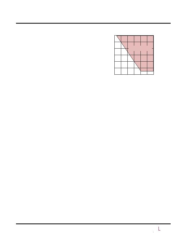
The LTC1966 needs at least 2.7V for its power supply,
more for dual supply configurations. The range of allow-
able negative supply voltages (V
SS
) vs positive supply
voltages (V
DD
) is shown in Figure 10. Mathematically, the
V
SS
constraint is:
3 " (V
DD
2.7V) d V
SS
d GND
The LTC1966 has internal ESD absorption devices, which
are referenced to the V
DD
and V
SS
supplies. For effective
in-circuit ESD immunity, the V
DD
and V
SS
pins must be
connected to a low external impedance. This can be ac-
complished with low impedance power planes or simply
with the recommended 0.01礔 decoupling to ground on
each supply.
Up and Running!
If you have followed along this far, you should have the
LTC1966 up and running by now! Dont forget to enable
the device by grounding Pin 8, or driving it with a logic low.
Keep in mind that the LTC1966 output impedance is fairly
high, and that even the standard 10M?input impedance of
a digital multimeter (DMM) or a 10?scope probe will load
down the output enough to degrade its typical gain error
of 0.1%. In the end application circuit, either a buffer or
another component with an extremely high input impedance
(such as a dual slope integrating ADC) should be used.
For laboratory evaluation, it may suffice to use a bench
top DMM with the ability to disconnect the 10M?shunt.
If you are still having trouble, it may be helpful to skip
ahead a few pages and review the Troubleshooting Guide.
What About Response Time?
With a large value averaging capacitor, the LTC1966 can
easily perform RMS-to-DC conversion on low frequency
signals. It compares quite favorably in this regard to
prior generation products because nothing about the S
circuitry is temperature sensitive. So the RMS result doesnt
get distorted by signal driven thermal fluctuations like a
log/antilog circuit output does.
However, using large value capacitors results in a slow
response time. Figure 11 shows the rising and falling
step responses with a 1礔 averaging capacitor. Although
they both appear at first glance to be standard exponential
Figure 10. V
SS
Limits vs V
DD
V
DD
(V)
2.5
6
5
4
3
2
0
3 3.5 4 4.5
1966 F10
5 5.5
1
LTC1966
OPERATES IN THIS RANGE
相关PDF资料 |
PDF描述 |
|---|---|
| V48B28C250B | CONVERTER MOD DC/DC 28V 250W |
| VI-JVY-IZ | CONVERTER MOD DC/DC 3.3V 16.5W |
| LP2980IM5-3.8/NOPB | IC REG LDO 3.8V 50MA SOT23-5 |
| RAC30-05DA-E | CONV AC/DC 2A 6.5-18VIN 3.0-5.5V |
| CDRH6D28NP-470NC | POWER INDUCTOR 47UH 0.80A SMD |
相关代理商/技术参数 |
参数描述 |
|---|---|
| LTC1966IMS8 | 功能描述:IC PREC RMS/DC CONV MCRPWR 8MSOP RoHS:否 类别:集成电路 (IC) >> PMIC - RMS 至 DC 转换器 系列:- 标准包装:46 系列:- 电流 - 电源:1.2mA 电源电压:±18 V,36 V 安装类型:表面贴装 封装/外壳:16-SOIC(0.295",7.50mm 宽) 供应商设备封装:16-SOIC W 包装:管件 |
| LTC1966IMS8#PBF | 功能描述:IC PREC RMS/DC CONV MCRPWR 8MSOP RoHS:是 类别:集成电路 (IC) >> PMIC - RMS 至 DC 转换器 系列:- 标准包装:46 系列:- 电流 - 电源:1.2mA 电源电压:±18 V,36 V 安装类型:表面贴装 封装/外壳:16-SOIC(0.295",7.50mm 宽) 供应商设备封装:16-SOIC W 包装:管件 |
| LTC1966IMS8#TR | 功能描述:IC PREC RMS/DC CONV MCRPWR 8MSOP RoHS:否 类别:集成电路 (IC) >> PMIC - RMS 至 DC 转换器 系列:- 标准包装:46 系列:- 电流 - 电源:1.2mA 电源电压:±18 V,36 V 安装类型:表面贴装 封装/外壳:16-SOIC(0.295",7.50mm 宽) 供应商设备封装:16-SOIC W 包装:管件 |
| LTC1966IMS8#TRPBF | 功能描述:IC PREC RMS/DC CONV MCRPWR 8MSOP RoHS:是 类别:集成电路 (IC) >> PMIC - RMS 至 DC 转换器 系列:- 标准包装:46 系列:- 电流 - 电源:1.2mA 电源电压:±18 V,36 V 安装类型:表面贴装 封装/外壳:16-SOIC(0.295",7.50mm 宽) 供应商设备封装:16-SOIC W 包装:管件 |
| LTC1966IMS8PBF | 制造商:Linear Technology 功能描述:RMS-to-DC Converter Prec. uPower MSOP8 |
发布紧急采购,3分钟左右您将得到回复。