- 您现在的位置:买卖IC网 > PDF目录10169 > LTC2859CDD#TRPBF (Linear Technology)IC TXRX RS485 20MBPS 10-DFN PDF资料下载
参数资料
| 型号: | LTC2859CDD#TRPBF |
| 厂商: | Linear Technology |
| 文件页数: | 13/18页 |
| 文件大小: | 0K |
| 描述: | IC TXRX RS485 20MBPS 10-DFN |
| 标准包装: | 2,500 |
| 类型: | 收发器 |
| 驱动器/接收器数: | 1/1 |
| 规程: | RS485 |
| 电源电压: | 4.5 V ~ 5.5 V |
| 安装类型: | 表面贴装 |
| 封装/外壳: | 10-WFDFN 裸露焊盘 |
| 供应商设备封装: | 10-DFN(3x3) |
| 包装: | 带卷 (TR) |
LTC2859/LTC2861
4
285961fc
Note 1: Stresses beyond those listed under Absolute Maximum Ratings
may cause permanent damage to the device. Exposure to any Absolute
Maximum Rating condition for extended periods may affect device
reliability and lifetime..
Note 2: All currents into device pins are positive; all currents out of device
pins are negative. All voltages are referenced to device ground unless
otherwise specified.
SYMBOL
PARAMETER
CONDITIONS
MIN
TYP
MAX
UNITS
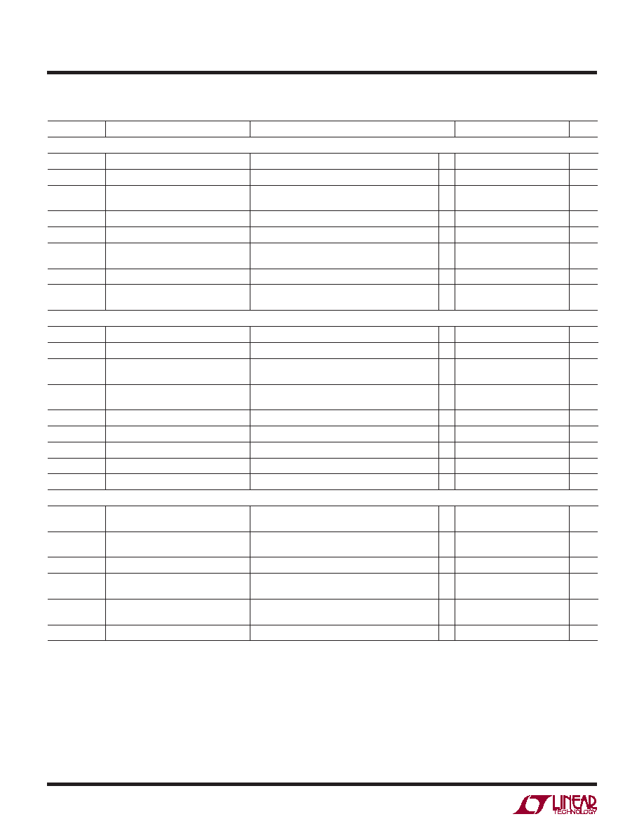
Driver in Normal Mode (SLO HIGH)
fMAX
Maximum Data Rate
Note 3
l
20
Mbps
tPLHD, tPHLD
Driver Input to Output
RDIFF = 54, CL = 100pF (Figure 3)
l
10
50
ns
DtPD
Driver Input to Output Difference
|tPLHD-tPHLD|
RDIFF = 54, CL = 100pF (Figure 3)
l
1
6
ns
tSKEWD
Driver Output Y to Output Z
RDIFF = 54, CL = 100pF (Figure 3)
l
1
±6
ns
tRD, tFD
Driver Rise or Fall Time
RDIFF = 54, CL = 100pF (Figure 3)
l
4
12.5
ns
tZLD, tZHD, tLZD,
tHZD
Driver Enable or Disable Time
RL = 500, CL = 50pF, RE = 0 (Figure 4)
l
70
ns
tZHSD, tZLSD
Driver Enable from Shutdown
RL = 500, CL = 50pF, RE = VCC (Figure 4)
l
8
s
tSHDN
Time to Shutdown
(DE =
↓, RE = VCC) or (DE = 0, RE ↑)
(Figure 4)
l
100
ns
Driver in SLO Mode (SLO LOW)
fMAXS
Maximum Data Rate
Note 3
l
250
kbps
tPLHDS, tPHLDS Driver Input to Output
RDIFF = 54, CL = 100pF (Figure 3)
l
0.95
1.5
s
DtPDS
Driver Input to Output Difference
|tPLHR-tPHLR|
RDIFF = 54, CL = 100pF (Figure 3)
l
50
500
ns
tSKEWDS
Driver Output A to Output B
RDIFF = 54, CL = 100pF (Figure 3)
(H-Grade)
l
200
±500
±750
ns
tRDS, tFDS
Driver Rise or Fall Time
RDIFF = 54, CL = 100pF (Figure 3)
l
0.9
1.5
s
tZHDS, tZLDS
Driver Enable Time
RL = 500, CL = 50pF, RE = 0 (Figure 4)
l
300
ns
tLZDS, tHZDS
Driver Disable Time
RL = 500, CL = 50pF, RE = 0 (Figure 4)
l
70
ns
tZHSDS, tZLSDS Driver Enable from Shutdown
RL = 500, CL = 50pF, RE = VCC (Figure 4)
l
8
s
tSHDNS
Time to Shutdown
(DE = 0, RE =
↑) or (DE = ↓, RE = VCC) (Figure 4)
l
500
ns
Receiver
tPLHR, tPHLR
Receiver Input to Output
CL = 15pF, VCM = 1.5V, |VAB| = 1.5V, tR and tF <
4ns (Figure 5)
l
50
70
ns
tSKEWR
Differential Receiver Skew
|tPLHR-tPHLR|
CL = 15pF (Figure 5)
l
1
6
ns
tRR, tFR
Receiver Output Rise or Fall Time
CL = 15pF (Figure 5)
l
3
12.5
ns
tZLR, tZHR, tLZR,
tHZR
Receiver Enable/Disable
RL = 1k, CL =15pF, DE = VCC (Figure 6)
DI = 0 or VCC
l
50
ns
tZHSR, tZLSR
Receiver Enable from Shutdown
RL = 1k, CL = 15pF, DE = 0V (Figure 6)
DI = 0 or VCC
l
8
s
tRTEN, tRTZ
Termination Enable or Disable Time
VB = 0V, VAB = 2V, RE = VCC, DE = 0V (Figure 7)
l
100
s
The l denotes the specifications which apply over the full operating
temperature range, otherwise specifications are at TA = 25°C, VCC = 5V, TE = 0 unless otherwise noted (Note 2).
Note 3: Maximum data rate is guaranteed by other measured parameters
and is not tested directly.
Note 4: This IC includes overtemperature protection that is intended
to protect the device during momentary overload conditions. Junction
temperature will exceed 125°C when overtemperature protection is active.
Continuous operation above the specified maximum operating junction
temperature may result in device degradation or failure.
swiTchinG characTerisTics
相关PDF资料 |
PDF描述 |
|---|---|
| 24282-31SG-300 | CONN RCPT 31POS PNL MNT SKT |
| VI-23L-MX-F4 | CONVERTER MOD DC/DC 28V 75W |
| VI-23L-MX-F3 | CONVERTER MOD DC/DC 28V 75W |
| AD7714ARSZ-5 | IC ADC 24BIT SIGMA-DELTA 28SSOP |
| VI-26D-CU-F1 | CONVERTER MOD DC/DC 85V 200W |
相关代理商/技术参数 |
参数描述 |
|---|---|
| LTC2859HDD#PBF | 功能描述:IC LINEAR RoHS:是 类别:集成电路 (IC) >> 接口 - 驱动器,接收器,收发器 系列:* 标准包装:27 系列:- 类型:收发器 驱动器/接收器数:3/3 规程:RS232,RS485 电源电压:4.75 V ~ 5.25 V 安装类型:表面贴装 封装/外壳:28-SOIC(0.295",7.50mm 宽) 供应商设备封装:28-SOIC 包装:管件 |
| LTC2859HDD#TRPBF | 功能描述:IC LINEAR RoHS:是 类别:集成电路 (IC) >> 接口 - 驱动器,接收器,收发器 系列:* 标准包装:27 系列:- 类型:收发器 驱动器/接收器数:3/3 规程:RS232,RS485 电源电压:4.75 V ~ 5.25 V 安装类型:表面贴装 封装/外壳:28-SOIC(0.295",7.50mm 宽) 供应商设备封装:28-SOIC 包装:管件 |
| LTC2859IDD | 制造商:Linear Technology 功能描述:Single Transmitter/Receiver RS-422/RS-485 10-Pin DFN EP |
| LTC2859IDD#PBF | 功能描述:IC TXRX RS485 20MBPS 10-DFN RoHS:是 类别:集成电路 (IC) >> 接口 - 驱动器,接收器,收发器 系列:- 产品培训模块:RS-232 & USB Transceiver 标准包装:2,000 系列:- 类型:收发器 驱动器/接收器数:1/1 规程:RS232 电源电压:3 V ~ 5.5 V 安装类型:表面贴装 封装/外壳:16-SSOP(0.209",5.30mm 宽) 供应商设备封装:16-SSOP 包装:带卷 (TR) 其它名称:296-19849-2 |
| LTC2859IDD#PBF | 制造商:Linear Technology 功能描述:IC RS-422/RS-485 TRANSCEIVER 5V DFN10 |
发布紧急采购,3分钟左右您将得到回复。