- 您现在的位置:买卖IC网 > PDF目录14841 > LTC3565EMSE#PBF (Linear Technology)IC REG BUCK SYNC ADJ 10MSOP PDF资料下载
参数资料
| 型号: | LTC3565EMSE#PBF |
| 厂商: | Linear Technology |
| 文件页数: | 11/22页 |
| 文件大小: | 0K |
| 描述: | IC REG BUCK SYNC ADJ 10MSOP |
| 标准包装: | 50 |
| 类型: | 降压(降压) |
| 输出类型: | 可调式 |
| 输出数: | 1 |
| 输出电压: | 0.6 V ~ 5 V |
| 输入电压: | 2.5 V ~ 5.5 V |
| PWM 型: | 电流模式,混合 |
| 频率 - 开关: | 最高 4MHz |
| 电流 - 输出: | 1.25A |
| 同步整流器: | 是 |
| 工作温度: | -40°C ~ 125°C |
| 安装类型: | 表面贴装 |
| 封装/外壳: | 10-TFSOP,10-MSOP(0.118",3.00mm 宽)裸露焊盘 |
| 包装: | 管件 |
| 供应商设备封装: | 10-MSOP 裸露焊盘 |
| 产品目录页面: | 1335 (CN2011-ZH PDF) |
�� �
�
�LTC3565�
�APPLICATIONS� INFORMATION�
�shows� some� typical� surface� mount� inductors� that� work�
�well� in� LTC3565� applications.�
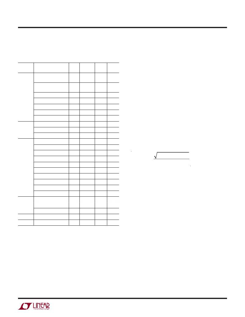
�Table� 1.� Representative� Surface� Mount� Inductors�
�MANU-� MAX� DC�
�FACTURER� PART� NUMBER� VALUE CURRENT� DCR� HEIGHT�
�Toko� A914BYW-1R2M=P3:� 1.2μH� 2.15A� 44mΩ� 2mm�
�D52LC�
�diode� peak� current� and� average� power� dissipation� so� as�
�not� to� exceed� the� diode� ratings.� The� main� problem� with�
�Schottky� diodes� is� that� their� parasitic� capacitance� reduces�
�the� efficiency,� usually� negating� the� possible� benefits� for�
�LTC3565� circuits.� Another� problem� that� a� Schottky� diode�
�can� introduce� is� higher� leakage� current� at� high� tempera-�
�tures,� which� could� reduce� the� low� current� efficiency.�
�A960AW-1R2M=P3:� 1.2μH�
�D518LC�
�DB3015C-1068AS-1R0N� 1.0μH�
�DB3018C-1069AS-1R0N� 1.0μH�
�1.8A�
�2.1A�
�2.1A�
�46m� 1.8mm�
�43m� 1.5mm�
�45m� 1.8mm�
�Remember� to� keep� lead� lengths� short� and� observe� proper�
�grounding� (see� Board� Layout� Considerations)� to� avoid� ring-�
�ing� and� increased� dissipation� when� using� a� catch� diode.�
�Coilcraft�
�Sumida�
�DB3020C-1070AS-1R0N� 1.0μH�
�A914BYW-2R2M-D52LC� 2.2μH�
�A915AY-2ROM-D53LC� 2.0μH�
�LPO1704-122ML� 1.2μH�
�D01608C-222� 2.2μH�
�LP01704-222M� 2.2μH�
�CR32-1R0� 1.0μH�
�CR5D11-1R0� 1.0μH�
�2.1A�
�2.05A�
�3.3A�
�2.1A�
�2.3A�
�2.4A�
�2.1A�
�2.2A�
�47m� 2mm�
�49m� 2mm�
�22m� 3mm�
�80m� 1mm�
�70m� 3mm�
�120m� 1mm�
�72m� 3mm�
�40m� 1.2mm�
�Input� Capacitor� (C� IN� )� Selection�
�In� continuous� mode,� the� input� current� of� the� converter� is� a�
�square� wave� with� a� duty� cycle� of� approximately� V� OUT� /V� IN� .�
�To� prevent� large� voltage� transients,� a� low� equivalent� series�
�resistance� (ESR)� input� capacitor� sized� for� the� maximum�
�RMS� current� must� be� used.� The� maximum� RMS� capacitor�
�current� is� given� by:�
�CDRH3D14-1R2�
�CDRH4D18C/LD-1R1�
�CDRH4D28C/LD-1R0�
�1.2μH�
�1.1μH�
�1.0μH�
�2.2A�
�2.1A�
�3.0A�
�36m� 1.5mm�
�24m� 2mm�
�17.5m� 3mm�
�I� RMS� ≈� I� MAX�
�V� OUT� (V� IN� ?� V� OUT� )�
�V� IN�
�CDRH4D28C-1R1�
�CDRH4D28-1R2�
�CDRH6D12-1R0�
�1.1μH�
�1.2μH�
�1.0μH�
�3.8A�
�2.56A�
�2.80A�
�22m� 3mm�
�23.6m� 3mm�
�37.5m� 1.5mm�
�where� the� maximum� average� output� current� I� MAX� equals�
�the� peak� current� minus� half� the� peak-to-peak� ripple� cur-�
�rent,� I� MAX� ?� I� LIM� –� Δ� I� L� /2.�
�N06DB2R2M�
�2.2μH�
�3.2A�
�29m� 3.2mm�
�CDRH4D282R2 2.2μH 2.04A 23mΩ 3mm�
�CDC5D232R2� 2.2μH� 2.16A� 30mΩ� 2.5mm�
�Taiyo� NPO3SB1ROM� 1.0μH� 2.6A� 27mΩ� 1.8mm�
�Yuden�
�N05DB2R2M� 2.2μH� 2.9A� 32mΩ� 2.8mm�
�Murata� LQN6C2R2M04� 2.2μH� 3.2A� 24mΩ� 5mm�
�FDK� MIPW3226DORGM� 0.9μH� 1.4A� 80mΩ� 1mm�
�Catch� Diode� Selection�
�Although� unnecessary� in� most� applications,� a� small�
�improvement� in� efficiency� can� be� obtained� in� a� few� ap-�
�plications� by� including� the� optional� diode� D1� shown� in�
�Figure� 2,� which� conducts� when� the� synchronous� switch�
�is� off.� When� using� Burst� Mode� operation� or� pulse� skip�
�mode,� the� synchronous� switch� is� turned� off� at� a� low�
�current� and� the� remaining� current� will� be� carried� by� the�
�optional� diode.� It� is� important� to� adequately� specify� the�
�This� formula� has� a� maximum� at� V� IN� =� 2V� OUT� ,� where�
�I� RMS� =� I� OUT� /2.� This� simple� worst� case� is� commonly� used�
�to� design� because� even� significant� deviations� do� not� offer�
�much� relief.� Note� that� capacitor� manufacturer’s� ripple� cur-�
�rent� ratings� are� often� based� on� only� 2000� hours� lifetime.�
�This� makes� it� advisable� to� further� derate� the� capacitor,�
�or� choose� a� capacitor� rated� at� a� higher� temperature� than�
�required.� Several� capacitors� may� also� be� paralleled� to� meet�
�the� size� or� height� requirements� of� the� design.� An� additional�
�0.1μF� to� 1μF� ceramic� capacitor� is� also� recommended� on�
�V� IN� for� high� frequency� decoupling,� when� not� using� an� all�
�ceramic� capacitor� solution.�
�Output� Capacitor� (C� OUT� )� Selection�
�The� selection� of� C� OUT� is� driven� by� the� required� ESR� to�
�minimize� voltage� ripple� and� load� step� transients.� Typically,�
�once� the� ESR� requirement� is� satisfied,� the� capacitance�
�3565fc�
�For� more� information� www.linear.com/LTC3565�
�11�
�相关PDF资料 |
PDF描述 |
|---|---|
| ISC1812EB391J | INDUCTOR WW 390UH 5% 1812 |
| LT1610IS8#PBF | IC REG BOOST ADJ 0.6A 8SOIC |
| ISC1812EB102J | INDUCTOR WW 1000UH 5% 1812 |
| LTC3565EDD#PBF | IC REG BUCK SYNC ADJ 1.25A 10DFN |
| ECC18DRES-S734 | CONN EDGECARD 36POS .100 EYELET |
相关代理商/技术参数 |
参数描述 |
|---|---|
| LTC3565EMSETRPBF | 制造商:LINER 制造商全称:Linear Technology 功能描述:1.25A, 4MHz, Synchronous Step-Down DC/DC Converter |
| LTC3565EMSE-TRPBF | 制造商:LINER 制造商全称:Linear Technology 功能描述:1.25A, 4MHz, Synchronous Step-Down DC/DC Converter |
| LTC3565IDD | 制造商:LINER 制造商全称:Linear Technology 功能描述:1.25A, 4MHz, Synchronous Step-Down DC/DC Converter |
| LTC3565IDD#PBF | 功能描述:IC REG BUCK SYNC ADJ 1.25A 10DFN RoHS:是 类别:集成电路 (IC) >> PMIC - 稳压器 - DC DC 开关稳压器 系列:- 标准包装:2,500 系列:- 类型:升压(升压) 输出类型:可调式 输出数:1 输出电压:1.24 V ~ 30 V 输入电压:1.5 V ~ 12 V PWM 型:电流模式,混合 频率 - 开关:600kHz 电流 - 输出:500mA 同步整流器:无 工作温度:-40°C ~ 85°C 安装类型:表面贴装 封装/外壳:8-SOIC(0.154",3.90mm 宽) 包装:带卷 (TR) 供应商设备封装:8-SOIC |
| LTC3565IDD#TRPBF | 功能描述:IC REG BUCK SYNC ADJ 1.25A 10DFN RoHS:是 类别:集成电路 (IC) >> PMIC - 稳压器 - DC DC 开关稳压器 系列:- 标准包装:2,500 系列:- 类型:升压(升压) 输出类型:可调式 输出数:1 输出电压:1.24 V ~ 30 V 输入电压:1.5 V ~ 12 V PWM 型:电流模式,混合 频率 - 开关:600kHz 电流 - 输出:500mA 同步整流器:无 工作温度:-40°C ~ 85°C 安装类型:表面贴装 封装/外壳:8-SOIC(0.154",3.90mm 宽) 包装:带卷 (TR) 供应商设备封装:8-SOIC |
发布紧急采购,3分钟左右您将得到回复。