参数资料
| 型号: | LTC3604IUD#TRPBF |
| 厂商: | Linear Technology |
| 文件页数: | 10/24页 |
| 文件大小: | 0K |
| 描述: | IC REG BUCK SYNC 2.5A 16QFN |
| 标准包装: | 2,500 |
| 类型: | 降压(降压) |
| 输出数: | 1 |
| 输入电压: | 3.6 V ~ 15 V |
| PWM 型: | 电流模式,混合 |
| 频率 - 开关: | 800kHz ~ 4MHz |
| 电流 - 输出: | 2.5A |
| 同步整流器: | 是 |
| 工作温度: | -40°C ~ 125°C |
| 安装类型: | 表面贴装 |
| 封装/外壳: | 16-WFQFN 裸露焊盘 |
| 包装: | 带卷 (TR) |
| 供应商设备封装: | 16-QFN-EP(3x3) |
�� �
�
�LTC3604�
�APPLICATIONS� INFORMATION�
�Δ� I� L� =� ?� OUT� ?� ?� 1� –� OUT� ?�
�R� RT� =�
�V� OUT� ?�
�?� ?� ?�
�L� =� ?�
�?� ?�
�?�
�V� OUT�
�?� f� ?� Δ� I� L� (� MAX� )� ?� ?�
�AgeneralLTC3604applicationcircuitisshownonthe?rst�
�page� of� this� data� sheet.� External� component� selection� is�
�largely� driven� by� the� load� requirement� and� begins� with� the�
�selection� of� the� inductor� L.� Once� the� inductor� is� chosen,� the�
�input� capacitor,� C� IN� ,� the� output� capacitor,� C� OUT� ,� the� internal�
�regulator� capacitor,� C� INTVCC� ,� and� the� boost� capacitor,� C� BOOST� ,�
�can� be� selected.� Next,� the� feedback� resistors� are� selected� to�
�set� the� desired� output� voltage.� Finally,� the� remaining� option-�
�al� external� components� can� be� selected� for� functions� such�
�as� external� loop� compensation,� track/soft-start,� externally�
�programmed� oscillator� frequency� and� PGOOD.�
�Operating� Frequency�
�Selection� of� the� operating� frequency� is� a� trade-off� between�
�ef?ciency� and� component� size.� High� frequency� operation�
�allows� the� use� of� smaller� inductor� and� capacitor� values.�
�Operation� at� lower� frequencies� improves� ef?ciency� by�
�reducing� internal� gate� charge� losses� but� requires� larger�
�inductance� values� and/or� capacitance� to� maintain� low�
�output� ripple� voltage.�
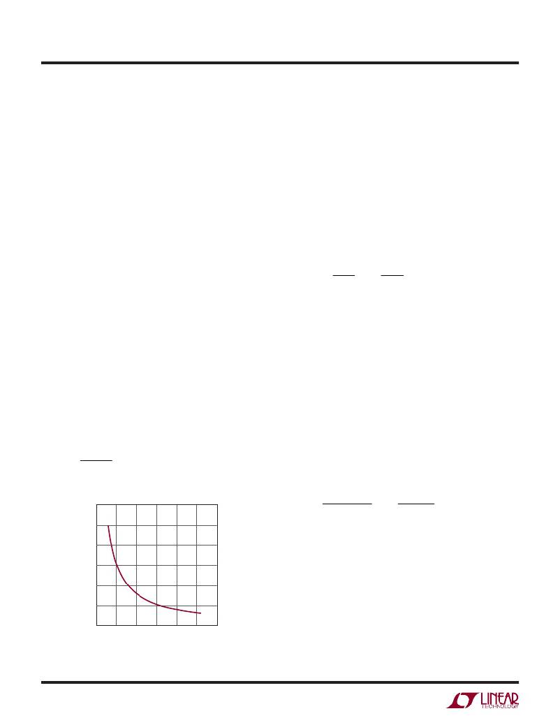
�The� operating� frequency,� f� O� ,� of� the� LTC3604� is� determined�
�by� an� external� resistor� that� is� connected� between� the� RT�
�pin� and� ground.� The� value� of� the� resistor� sets� the� ramp�
�current� that� is� used� to� charge� and� discharge� an� internal�
�timing� capacitor� within� the� oscillator� and� can� be� calculated�
�by� using� the� following� equation:�
�3.2 E11�
�f� O�
�where� R� RT� is� in� Ω� and� f� O� is� in� Hz.�
�6000�
�5000�
�4000�
�3000�
�2000�
�Connecting� the� RT� pin� to� INTV� CC� will� default� the� converter�
�to� f� O� =� 2MHz;� however,� this� switching� frequency� will� be�
�more� sensitive� to� process� and� temperature� variations� than�
�when� using� a� resistor� on� RT� (see� Typical� Performance�
�Characteristics).�
�Inductor� Selection�
�For� a� given� input� and� output� voltage,� the� inductor� value� and�
�operating� frequency� determine� the� inductor� ripple� current.�
�More� speci?cally,� the� inductor� ripple� current� decreases�
�with� higher� inductor� value� or� higher� operating� frequency�
�according� to� the� following� equation:�
�?� V� ?� ?� V� ?�
�?� f� ?� L� ?� ?� V� IN� ?�
�where� Δ� I� L� =� inductor� ripple� current,� f� =� operating� frequency�
�and� L� =� inductor� value.� A� trade-off� between� component�
�size,� ef?ciency� and� operating� frequency� can� be� seen� from�
�this� equation.� Accepting� larger� values� of� Δ� I� L� allows� the�
�use� of� lower� value� inductors� but� results� in� greater� core�
�loss� in� the� inductor,� greater� ESR� loss� in� the� output� capaci-�
�tor,� and� larger� output� ripple.� Generally,� highest� ef?ciency�
�operation� is� obtained� at� low� operating� frequency� with�
�small� ripple� current.�
�A� reasonable� starting� point� for� setting� the� ripple� current� is�
�about� 40%� of� I� OUT(MAX)� .� Note� that� the� largest� ripple� current�
�occurs� at� the� highest� V� IN� .� To� guarantee� the� ripple� current�
�does� not� exceed� a� speci?ed� maximum� the� inductance�
�should� be� chosen� according� to:�
�1� –�
�V� IN� (� MAX� )� ?�
�Once� the� value� for� L� is� known� the� type� of� inductor� must�
�be� selected.� Actual� core� loss� is� independent� of� core� size�
�for� a� ?xed� inductor� value� but� is� very� dependent� on� the�
�inductance� selected.� As� the� inductance� increases,� core� loss�
�decreases.� Unfortunately,� increased� inductance� requires�
�more� turns� of� wire� leading� to� increased� copper� loss.�
�1000�
�Ferrite� designs� exhibit� very� low� core� loss� and� are� pre-�
�0�
�0�
�100�
�200�
�300� 400�
�R� T� (kΩ)�
�500�
�600�
�ferred� at� high� switching� frequencies,� so� design� goals� can�
�concentrate� on� copper� loss� and� preventing� saturation.�
�3604� F01�
�Figure� 1.� Switching� Frequency� vs� R� T�
�Ferrite� core� materials� saturate� “hard,”� meaning� the� induc-�
�tance� collapses� abruptly� when� the� peak� design� current� is�
�3604f�
�10�
�相关PDF资料 |
PDF描述 |
|---|---|
| LTC3605IUF#PBF | IC REG BUCK SYNC ADJ 5A 24QFN |
| LTC3606BIDD#TRPBF | IC REG BUCK SYNC ADJ 0.8A 8DFN |
| LTC3608IWKG#PBF | IC REG BUCK SYNC ADJ 8A 52QFN |
| LTC3609IWKG#TRPBF | IC REG BUCK SYNC ADJ 6A 52QFN |
| LTC3610IWP#PBF | IC REG BUCK SYNC ADJ 12A 64QFN |
相关代理商/技术参数 |
参数描述 |
|---|---|
| LTC3605AEUF#PBF | 功能描述:IC REG BUCK SYNC ADJ 5A 24QFN RoHS:是 类别:集成电路 (IC) >> PMIC - 稳压器 - DC DC 开关稳压器 系列:- 设计资源:Design Support Tool 标准包装:1 系列:- 类型:升压(升压) 输出类型:固定 输出数:1 输出电压:3V 输入电压:0.75 V ~ 2 V PWM 型:- 频率 - 开关:- 电流 - 输出:100mA 同步整流器:是 工作温度:-40°C ~ 85°C 安装类型:表面贴装 封装/外壳:SOT-23-5 细型,TSOT-23-5 包装:剪切带 (CT) 供应商设备封装:TSOT-23-5 其它名称:AS1323-BTTT-30CT |
| LTC3605AEUF#TRPBF | 功能描述:IC REG BUCK SYNC ADJ 5A 24QFN RoHS:是 类别:集成电路 (IC) >> PMIC - 稳压器 - DC DC 开关稳压器 系列:- 设计资源:Design Support Tool 标准包装:1 系列:- 类型:升压(升压) 输出类型:固定 输出数:1 输出电压:3V 输入电压:0.75 V ~ 2 V PWM 型:- 频率 - 开关:- 电流 - 输出:100mA 同步整流器:是 工作温度:-40°C ~ 85°C 安装类型:表面贴装 封装/外壳:SOT-23-5 细型,TSOT-23-5 包装:剪切带 (CT) 供应商设备封装:TSOT-23-5 其它名称:AS1323-BTTT-30CT |
| LTC3605AIUF#PBF | 功能描述:IC REG BUCK SYNC ADJ 5A 24QFN RoHS:是 类别:集成电路 (IC) >> PMIC - 稳压器 - DC DC 开关稳压器 系列:- 设计资源:Design Support Tool 标准包装:1 系列:- 类型:升压(升压) 输出类型:固定 输出数:1 输出电压:3V 输入电压:0.75 V ~ 2 V PWM 型:- 频率 - 开关:- 电流 - 输出:100mA 同步整流器:是 工作温度:-40°C ~ 85°C 安装类型:表面贴装 封装/外壳:SOT-23-5 细型,TSOT-23-5 包装:剪切带 (CT) 供应商设备封装:TSOT-23-5 其它名称:AS1323-BTTT-30CT |
| LTC3605AIUF#TRPBF | 功能描述:IC REG BUCK SYNC ADJ 5A 24QFN RoHS:是 类别:集成电路 (IC) >> PMIC - 稳压器 - DC DC 开关稳压器 系列:- 设计资源:Design Support Tool 标准包装:1 系列:- 类型:升压(升压) 输出类型:固定 输出数:1 输出电压:3V 输入电压:0.75 V ~ 2 V PWM 型:- 频率 - 开关:- 电流 - 输出:100mA 同步整流器:是 工作温度:-40°C ~ 85°C 安装类型:表面贴装 封装/外壳:SOT-23-5 细型,TSOT-23-5 包装:剪切带 (CT) 供应商设备封装:TSOT-23-5 其它名称:AS1323-BTTT-30CT |
| LTC3605EUF#PBF | 功能描述:IC REG BUCK SYNC ADJ 5A 24QFN RoHS:是 类别:集成电路 (IC) >> PMIC - 稳压器 - DC DC 开关稳压器 系列:- 标准包装:250 系列:- 类型:降压(降压) 输出类型:固定 输出数:1 输出电压:1.2V 输入电压:2.05 V ~ 6 V PWM 型:电压模式 频率 - 开关:2MHz 电流 - 输出:500mA 同步整流器:是 工作温度:-40°C ~ 85°C 安装类型:表面贴装 封装/外壳:6-UFDFN 包装:带卷 (TR) 供应商设备封装:6-SON(1.45x1) 产品目录页面:1032 (CN2011-ZH PDF) 其它名称:296-25628-2 |
发布紧急采购,3分钟左右您将得到回复。