- 您现在的位置:买卖IC网 > PDF目录240302 > LTC3634EUFD#TRPBF (LINEAR TECHNOLOGY CORP) 5.5 A DUAL SWITCHING CONTROLLER, 4600 kHz SWITCHING FREQ-MAX, PQCC28 PDF资料下载
参数资料
| 型号: | LTC3634EUFD#TRPBF |
| 厂商: | LINEAR TECHNOLOGY CORP |
| 元件分类: | 稳压器 |
| 英文描述: | 5.5 A DUAL SWITCHING CONTROLLER, 4600 kHz SWITCHING FREQ-MAX, PQCC28 |
| 封装: | 4 X 5 MM, LEAD FREE, PLASTIC, MO-220, QFN-28 |
| 文件页数: | 7/28页 |
| 文件大小: | 359K |
| 代理商: | LTC3634EUFD#TRPBF |
第1页第2页第3页第4页第5页第6页当前第7页第8页第9页第10页第11页第12页第13页第14页第15页第16页第17页第18页第19页第20页第21页第22页第23页第24页第25页第26页第27页第28页
LTC3634
15
3634f
When SW1 and SW2 operate 180° out-of-phase, the
worst-case input RMS current occurs when the VTTsupply
is sinking current and VDDQ is sourcing the same amount
of current. Knowing that VOUT2 = one-half VOUT1 in the
DDR application, the input RMS current in this case is
given by:
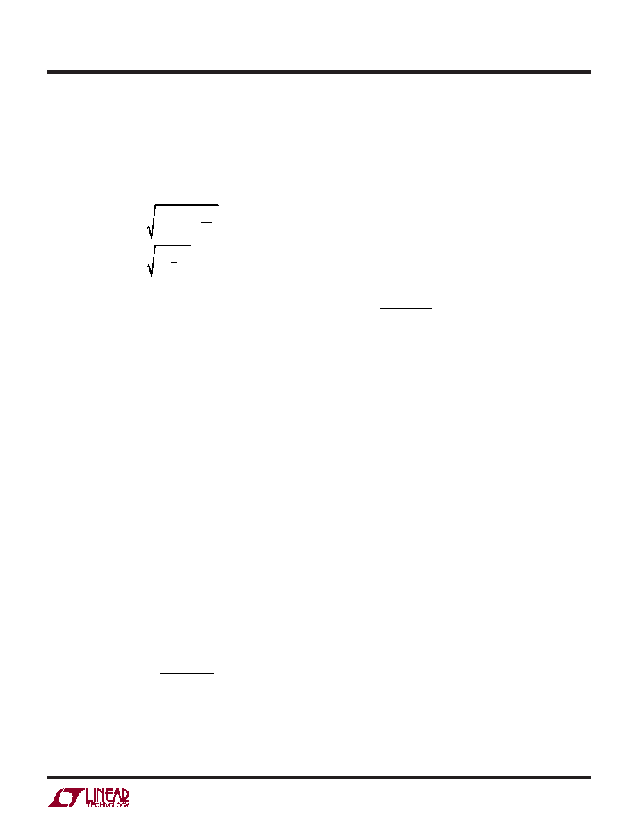
IRMS = IOUT(MAX) D1 1.5
D1
4
for D1 < 0.5
IRMS = IOUT(MAX) 1
3
4
D1 for D1 > 0.5
where D1 is the duty cycle of channel 1 (VDDQ supply).
These equations show that maximum IRMS occurs at
50% duty cycle (VIN = 2 VOUT1). This simple worst-case
condition may be used for design as deviations in duty
cycle do not offer significant relief. Note that ripple current
ratings from capacitor manufacturers are often based on
only 2000 hours of life which makes it advisable to further
derate the capacitor, or choose a capacitor rated at a higher
temperature than required.
Several capacitors may also be paralleled to meet size or
height requirements in the design. For low input voltage
applications, sufficient bulk input capacitance is needed
to minimize transient effects during output load changes.
Even though the LTC3634 design includes an overvoltage
protection circuit, care must always be taken to ensure
input voltage transients do not pose an overvoltage haz-
ard to the part.
The selection of COUT is determined by the effective series
resistance(ESR)thatisrequiredtominimizevoltageripple
and load step transients as well as the amount of bulk
capacitance that is necessary to ensure that the control
loop is stable. Loop stability can be checked by viewing
the load transient response. The output ripple, ΔVOUT, is
approximated by:
VOUT < IL ESR+
1
8 f COUT
When using low-ESR ceramic capacitors, it is more use-
ful to choose the output capacitor value to fulfill a charge
applicaTions inForMaTion
storagerequirement.Duringaloadstep,theoutputcapaci-
tor must instantaneously supply the current to support
the load until the feedback loop raises the switch current
enough to support the load. The time required for the
feedback loop to respond is dependent on the compensa-
tion and the output capacitor size. Typically, three to four
cycles are required to respond to a load step, but only in
the first cycle does the output drop linearly. The output
droop, VDROOP,isusuallyaboutthreetimesthelineardrop
of the first cycle, provided the loop crossover frequency is
maximized. Thus, a good place to start is with the output
capacitor size of approximately:
COUT ≈
3
IOUT
f VDROOP
Thoughthisequationprovidesagoodapproximation,more
capacitance may be required depending on the duty cycle
and load step requirements. The actual VDROOP should be
verified by applying a load step to the output.
Using Ceramic Input and Output Capacitors
Higher values, lower cost ceramic capacitors are available
in small case sizes. Their high ripple current, high voltage
ratingandlowESRmakethemidealforswitchingregulator
applications. However, due to the self-resonant and high-
Q characteristics of some types of ceramic capacitors,
care must be taken when these capacitors are used at
the input. When a ceramic capacitor is used at the input
and the power is supplied by a wall adapter through long
wires, a load step at the output can induce ringing at the
VIN input. At best, this ringing can couple to the output
and be mistaken as loop instability. At worst, a sudden
inrush of current through the long wires can potentially
cause a voltage spike at VIN large enough to damage the
part. For a more detailed discussion, refer to Application
Note 88.
When choosing the input and output ceramic capacitors,
choose the X5R and X7R dielectric formulations. These
dielectrics have the best temperature and voltage charac-
teristics of all the ceramics for a given value and size.
相关PDF资料 |
PDF描述 |
|---|---|
| LPA15DP | 2-OUTPUT 65 W DC-DC REG PWR SUPPLY MODULE |
| LS4001-9RD8TB1 | 1-OUTPUT 100 W AC-DC PWR FACTOR CORR MODULE |
| LK1601-7ERD3TB1 | 1-OUTPUT 150 W AC-DC REG PWR SUPPLY MODULE |
| LT1236BIN-5 | 1-OUTPUT THREE TERM VOLTAGE REFERENCE, 5 V, PDIP |
| LS1001-7PD4 | 1-OUTPUT AC-DC REG PWR SUPPLY MODULE |
相关代理商/技术参数 |
参数描述 |
|---|---|
| LTC3634HFE#PBF | 制造商:Linear Technology 功能描述:IC CONV DDR DDR2 DDR3 28TSSOP 制造商:Linear Technology 功能描述:BUCK 15V 3A 500KHZ-4MHZ TS 制造商:Linear Technology 功能描述:DP-SWREG/Monolithic, 15V Dual 3A Monolithic Step Down Regulator for DDR Power 制造商:Linear Technology 功能描述:DC-DC REGULATOR, BUCK, ADJ, TSSOP-28, Primary Input Voltage:15V, No. of Outputs:2, Output Current:3A, No. of Pins:28, Operating Temperature Min:-40C, Operating Temperature Max:150C, MSL:MSL 1 - Unlimited, Package / Case:28-TSSOP , RoHS Compliant: Yes |
| LTC3634HFE#TRPBF | 制造商:Linear Technology 功能描述:IC REG 15V 3A STEP DOWN 28-TSSOP |
| LTC3634HUFD#PBF | 制造商:Linear Technology 功能描述:IC CONV DDR DDR2 DDR3 28-QFN 制造商:Linear Technology 功能描述:BUCK 15V 3A 500KHZ-4MHZ QF 制造商:Linear Technology 功能描述:DC-DC REGULATOR, BUCK, ADJ, QFN-28, Primary Input Voltage:15V, No. of Outputs:2, Output Current:3A, No. of Pins:28, Operating Temperature Min:-40C, Operating Temperature Max:150C, MSL:MSL 1 - Unlimited, Package / Case:28-QFN , RoHS Compliant: Yes |
| LTC3634HUFD#TRPBF | 制造商:Linear Technology 功能描述:IC REG 15V 3A STEP DOWN 28-QFN 制造商:Linear Technology 功能描述:DC-DC REGULATOR, BUCK, ADJ, QFN-28, Primary Input Voltage:15V, No. of Outputs:2, Output Current:3A, No. of Pins:28, Operating Temperature Min:-40C, Operating Temperature Max:150C, MSL:-, Package / Case:28-QFN , RoHS Compliant: Yes |
| LTC3634IFE#PBF | 功能描述:IC CONV DDR DDR2 DDR3 28TSSOP RoHS:是 类别:集成电路 (IC) >> PMIC - 稳压器 - 专用型 系列:- 标准包装:43 系列:- 应用:控制器,Intel VR11 输入电压:5 V ~ 12 V 输出数:1 输出电压:0.5 V ~ 1.6 V 工作温度:-40°C ~ 85°C 安装类型:表面贴装 封装/外壳:48-VFQFN 裸露焊盘 供应商设备封装:48-QFN(7x7) 包装:管件 |
发布紧急采购,3分钟左右您将得到回复。