- 您现在的位置:买卖IC网 > PDF目录16048 > LTC4065AEDC#TRM (Linear Technology)IC CHARGER BATT LI-ON 6-DFN PDF资料下载
参数资料
| 型号: | LTC4065AEDC#TRM |
| 厂商: | Linear Technology |
| 文件页数: | 13/16页 |
| 文件大小: | 0K |
| 描述: | IC CHARGER BATT LI-ON 6-DFN |
| 标准包装: | 500 |
| 功能: | 充电管理 |
| 电池化学: | 锂离子(Li-Ion) |
| 电源电压: | 3.75 V ~ 5.5 V |
| 工作温度: | -40°C ~ 85°C |
| 安装类型: | 表面贴装 |
| 封装/外壳: | 6-WFDFN 裸露焊盘 |
| 供应商设备封装: | 6-DFN-EP(2x2) |
| 包装: | 带卷 (TR) |
| 其它名称: | LTC4065AEDC-ND |
�� �
�
�LTC4065/LTC4065A�
�APPLICATIO� S� I� FOR� ATIO�
�Undervoltage� Charge� Current� Limiting� (UVCL)�
�The� LTC4065/LTC4065A� includes� undervoltage� charge�
�(� ?� V� UVCL1� )� current� limiting� that� prevents� full� charge� cur-�
�rent� until� the� input� supply� voltage� reaches� approximately�
�200mV� above� the� battery� voltage.� This� feature� is� particu-�
�larly� useful� if� the� LTC4065� is� powered� from� a� supply� with�
�long� leads� (or� any� relatively� high� output� impedance).�
�For� example,� USB-powered� systems� tend� to� have� highly�
�variable� source� impedances� (due� primarily� to� cable� quality�
�and� length).� A� transient� load� combined� with� such� imped-�
�ance� can� easily� trip� the� UVLO� threshold� and� turn� the�
�charger� off� unless� undervoltage� charge� current� limiting� is�
�implemented.�
�Consider� a� situation� where� the� LTC4065� is� operating�
�under� normal� conditions� and� the� input� supply� voltage�
�begins� to� droop� (e.g.,� an� external� load� drags� the� input�
�supply� down).� If� the� input� voltage� reaches� V� BAT� +� ?� V� UVCL1�
�(approximately� 220mV� above� the� battery� voltage),�
�undervoltage� charge� current� limiting� will� begin� to� reduce�
�the� charge� current� in� an� attempt� to� maintain� ?� V� UVCL1�
�between� the� V� CC� input� and� the� BAT� output� of� the� IC.� The�
�LTC4065� will� continue� to� operate� at� the� reduced� charge�
�current� until� the� input� supply� voltage� is� increased� or�
�voltage� mode� reduces� the� charge� current� further.�
�Operation� from� Current� Limited� Wall� Adapter�
�than� 600mA.� Since� the� LTC4065� will� demand� a� charge�
�current� higher� than� the� current� limit� of� the� voltage� supply,�
�the� supply� voltage� will� drop� to� the� battery� voltage� plus�
�600mA� times� the� “on”� resistance� of� the� internal� PFET.� The�
�“on”� resistance� of� the� LTC4065� power� device� is� approxi-�
�mately� 450m� ?� with� a� 5V� supply.� The� actual� “on”� resis-�
�tance� will� be� slightly� higher� due� to� the� fact� that� the� input�
�supply� will� drop� to� less� than� 5V.� The� power� dissipated�
�during� this� phase� of� charging� is� less� than� 240mW.� That� is�
�a� 76%� improvement� over� the� non-current� limited� supply�
�power� dissipation.�
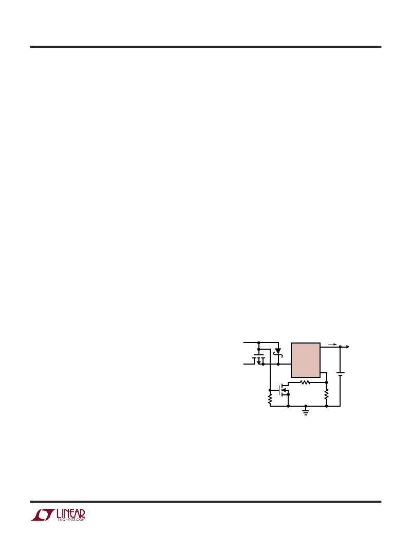
�USB� and� Wall� Adapter� Power�
�Although� the� LTC4065/LTC4065A� allow� charging� from� a�
�USB� port,� a� wall� adapter� can� also� be� used� to� charge� Li-Ion�
�batteries.� Figure� 3� shows� an� example� of� how� to� combine�
�wall� adapter� and� USB� power� inputs.� A� P-channel� MOSFET,�
�MP1,� is� used� to� prevent� back� conducting� into� the� USB� port�
�when� a� wall� adapter� is� present� and� Schottky� diode,� D1,� is�
�used� to� prevent� USB� power� loss� through� the� 1k� pull-down�
�resistor.�
�Typically� a� wall� adapter� can� supply� significantly� more�
�current� than� the� 500mA-limited� USB� port.� Therefore,� an�
�N-channel� MOSFET,� MN1,� and� an� extra� program� resistor�
�are� used� to� increase� the� charge� current� to� 750mA� when� the�
�wall� adapter� is� present.�
�By� using� a� current� limited� wall� adapter� as� the� input�
�supply,� the� LTC4065� dissipates� significantly� less� power�
�when� programmed� for� a� current� higher� than� the� limit� of�
�the� supply� as� compared� to� using� a� non-current� limited�
�supply� at� the� same� charge� current.�
�5V� WALL�
�ADAPTER�
�750mA�
�I� CHG�
�USB�
�POWER�
�500mA�
�MP1�
�D1�
�4�
�BAT�
�LTC4065�
�V� CC�
�PROG�
�3�
�6�
�I� CHG�
�+�
�SYSTEM�
�LOAD�
�Li-Ion�
�BATTERY�
�Consider� a� situation� where� an� application� demands� a�
�600mA� charge� current� for� an� 800mAh� Li-Ion� battery.� If� a�
�I� CHG�
�1k�
�MN1� 4.02k�
�2k�
�typical� 5V� (non-current� limited)� input� supply� is� available�
�then� the� peak� power� dissipation� inside� the� part� can�
�exceed� 1W.�
�Now� consider� the� same� scenario,� but� with� a� 5V� input�
�supply� with� a� 600mA� current� limit.� To� take� advantage� of�
�the� supply,� it� is� necessary� to� program� the� LTC4065� to�
�charge� at� a� current� above� 600mA.� Assume� that� the� LTC4065�
�is� programmed� for� 650mA� (i.e.,� R� PROG� =� 1.54k)� to� ensure�
�that� part� tolerances� maintain� a� programmed� current� higher�
�4065� F03�
�Figure� 3.� Combining� Wall� Adapter� and� USB� Power�
�Stability� Considerations�
�The� LTC4065/LTC4065A� contain� two� control� loops:� con-�
�stant-voltage� and� constant-current.� The� constant-voltage�
�loop� is� stable� without� any� compensation� when� a� battery� is�
�connected� with� low� impedance� leads.� Excessive� lead�
�4065fb�
�13�
�相关PDF资料 |
PDF描述 |
|---|---|
| GMC13DRTI-S13 | CONN EDGECARD 26POS .100 EXTEND |
| LTC1998CS6#TRPBF | IC DETECT VOLT PR LOBATT SOT23-6 |
| 5606125 | ANT EXT CABLE 20FT N ML-N ML |
| LHL10NB271K | INDUCTOR 270UH .70A RADIAL |
| ADM809SAKSZ-REEL7 | IC SUPERVISOR MPU 2.93V SC-70-3 |
相关代理商/技术参数 |
参数描述 |
|---|---|
| LTC4065EDC | 制造商:LINER 制造商全称:Linear Technology 功能描述:Standalone 750mA Li-Ion Battery Charger in 2 】 2 DFN |
| LTC4065EDC#PBF | 制造商:Linear Technology 功能描述:BATTERY CHARGER LI-ION 750mA 制造商:Linear Technology 功能描述:BATTERY CHARGER, LI-ION, 750mA, DFN-6; Battery Type:Li-Ion; Input Voltage:5.5V; Battery Charge Voltage:4.2V; Charge Current Max:750mA; Battery IC Case Style:DFN; No. of Pins:6; No. of Series Cells:1; Operating Temperature Min:-40C ;RoHS Compliant: Yes |
| LTC4065EDC#TR | 功能描述:IC CHARGER BATT LI-ON 6-DFN RoHS:否 类别:集成电路 (IC) >> PMIC - 电池管理 系列:- 标准包装:61 系列:- 功能:电源管理 电池化学:锂离子(Li-Ion)、锂聚合物(Li-Pol) 电源电压:4.35 V ~ 5.5 V 工作温度:-40°C ~ 85°C 安装类型:表面贴装 封装/外壳:22-WFDFN 裸露焊盘 供应商设备封装:22-DFN(6x3)裸露焊盘 包装:管件 |
| LTC4065EDC#TRM | 功能描述:IC CHARGER BATT LI-ON 6-DFN RoHS:否 类别:集成电路 (IC) >> PMIC - 电池管理 系列:- 标准包装:61 系列:- 功能:电源管理 电池化学:锂离子(Li-Ion)、锂聚合物(Li-Pol) 电源电压:4.35 V ~ 5.5 V 工作温度:-40°C ~ 85°C 安装类型:表面贴装 封装/外壳:22-WFDFN 裸露焊盘 供应商设备封装:22-DFN(6x3)裸露焊盘 包装:管件 |
| LTC4065EDC#TRMPBF | 功能描述:IC CHARGER BATT LI-ON 6-DFN RoHS:是 类别:集成电路 (IC) >> PMIC - 电池管理 系列:- 其它有关文件:STC3100 View All Specifications 特色产品:STC3100 - Battery Monitor IC 标准包装:4,000 系列:- 功能:燃料,电量检测计/监控器 电池化学:锂离子(Li-Ion) 电源电压:2.7 V ~ 5.5 V 工作温度:-40°C ~ 85°C 安装类型:表面贴装 封装/外壳:8-TSSOP,8-MSOP(0.118",3.00mm 宽) 供应商设备封装:8-MiniSO 包装:带卷 (TR) 其它名称:497-10526-2 |
发布紧急采购,3分钟左右您将得到回复。