- 您现在的位置:买卖IC网 > PDF目录80226 > LTC4065EDC-4.4#TRM (LINEAR TECHNOLOGY CORP) 1-CHANNEL POWER SUPPLY SUPPORT CKT, PDSO6 PDF资料下载
参数资料
| 型号: | LTC4065EDC-4.4#TRM |
| 厂商: | LINEAR TECHNOLOGY CORP |
| 元件分类: | 电源管理 |
| 英文描述: | 1-CHANNEL POWER SUPPLY SUPPORT CKT, PDSO6 |
| 封装: | 2 X 2 MM, PLASTIC, MO-229WCCD-2, DFN-6 |
| 文件页数: | 5/16页 |
| 文件大小: | 178K |
| 代理商: | LTC4065EDC-4.4#TRM |
13
LTC4065-4.4
406544f
Stability Considerations
The LTC4065-4.4 contain two control loops: constant-
voltage and constant-current. The constant-voltage loop
is stable without any compensation when a battery is
connected with low impedance leads. Excessive lead
length, however, may add enough series inductance to
require a bypass capacitor of at least 1
F from BAT to
GND. Furthermore, a 4.7
F capacitor with a 0.2 to 1
series resistor from BAT to GND is required to keep ripple
voltage low when the battery is disconnected.
High value capacitors with very low ESR (especially ce-
ramic) may reduce the constant-voltage loop phase mar-
gin. Ceramic capacitors up to 22
F may be used in parallel
with a battery, but larger ceramics should be decoupled
with 0.2
to 1 of series resistance.
In constant-current mode, the PROG pin is in the feedback
loop, not the battery. Because of the additional pole
created by the PROG pin capacitance, capacitance on this
pin must be kept to a minimum. With no additional
capacitance on the PROG pin, the charger is stable with
program resistor values as high as 25k. However, addi-
tional capacitance on this node reduces the maximum
allowed program resistor. The pole frequency at the PROG
pin should be kept above 100kHz. Therefore, if the PROG
pin is loaded with a capacitance, CPROG, the following
equation should be used to calculate the maximum resis-
tance value for RPROG:
R
C
PROG
≤
π
1
2105
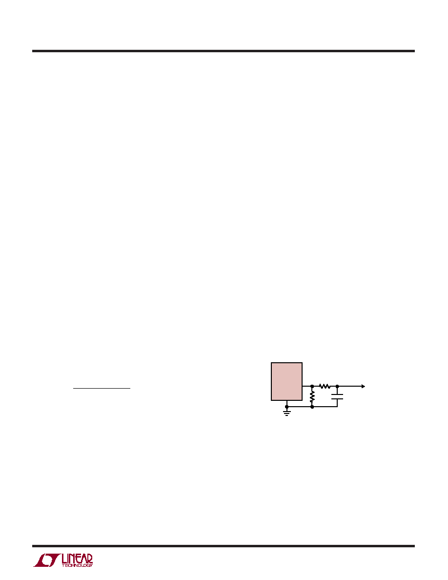
Average, rather than instantaneous, battery current may
be of interest to the user. For example, if a switching power
supply operating in low current mode is connected in
parallel with the battery, the average current being pulled
out of the BAT pin is typically of more interest than the
instantaneous current pulses. In such a case, a simple RC
filter can be used on the PROG pin to measure the average
battery current as shown in Figure 4. A 10K resistor has
been added between the PROG pin and the filter capacitor
to ensure stability.
Power Dissipation
The conditions that cause the LTC4065-4.4 to reduce
charge current through thermal feedback can be approxi-
mated by considering the power dissipated in the IC. For
high charge currents, the LTC4065-4.4 power dissipation
is approximately:
PD = (VCC – VBAT) IBAT
Where PD is the power dissipated, VCC is the input supply
voltage, VBAT is the battery voltage and IBAT is the charge
current. It is not necessary to perform any worst-case
power dissipation scenarios because the LTC4065-4.4
will automatically reduce the charge current to maintain
the die temperature at approximately 115
°C. However, the
approximate ambient temperature at which the thermal
feedback begins to protect the IC is:
TA = 115°C – PD θJA
TA = 115°C – (VCC – VBAT) IBAT θJA
Figure 4. Isolating Capacitive Load on the PROG Pin and Filtering
APPLICATIO S I FOR ATIO
WU
UU
4065 F04
CFILTER
CHARGE
CURRENT
MONITOR
CIRCUITRY
RPROG
LTC4065-4.4
PROG
GND
10k
相关PDF资料 |
PDF描述 |
|---|---|
| LS4601-7ERD7T | 1-OUTPUT 100 W AC-DC PWR FACTOR CORR MODULE |
| LS4001-7PD1TB1 | 1-OUTPUT 100 W AC-DC PWR FACTOR CORR MODULE |
| LS4001-9EPDDTB1 | 1-OUTPUT 100 W AC-DC PWR FACTOR CORR MODULE |
| LS4001-9ERD1TB1 | 1-OUTPUT 100 W AC-DC PWR FACTOR CORR MODULE |
| LS4001-9RD1B1 | 1-OUTPUT 100 W AC-DC PWR FACTOR CORR MODULE |
相关代理商/技术参数 |
参数描述 |
|---|---|
| LTC4065L | 制造商:LINEAR 制造商全称:LINEAR 功能描述:Standalone 250mA Li-Ion Battery Charger in 2 × 2 DFN |
| LTC4065L_12 | 制造商:LINEAR 制造商全称:LINEAR 功能描述:Standalone 250mA Li-Ion Battery Charger in 2 × 2 DFN |
| LTC4065LEDC#TRM | 制造商:Linear Technology 功能描述:BATT CHARGER LI ON 250MA 6DFN |
| LTC4065LEDC#TRMPBF | 功能描述:IC CHARGER LI-ION 6-DFN RoHS:是 类别:集成电路 (IC) >> PMIC - 电池管理 系列:- 其它有关文件:STC3100 View All Specifications 特色产品:STC3100 - Battery Monitor IC 标准包装:4,000 系列:- 功能:燃料,电量检测计/监控器 电池化学:锂离子(Li-Ion) 电源电压:2.7 V ~ 5.5 V 工作温度:-40°C ~ 85°C 安装类型:表面贴装 封装/外壳:8-TSSOP,8-MSOP(0.118",3.00mm 宽) 供应商设备封装:8-MiniSO 包装:带卷 (TR) 其它名称:497-10526-2 |
| LTC4065LEDC#TRPBF | 功能描述:IC CHARGER LI-ION 6-DFN RoHS:是 类别:集成电路 (IC) >> PMIC - 电池管理 系列:- 标准包装:61 系列:- 功能:电源管理 电池化学:锂离子(Li-Ion)、锂聚合物(Li-Pol) 电源电压:4.35 V ~ 5.5 V 工作温度:-40°C ~ 85°C 安装类型:表面贴装 封装/外壳:22-WFDFN 裸露焊盘 供应商设备封装:22-DFN(6x3)裸露焊盘 包装:管件 |
发布紧急采购,3分钟左右您将得到回复。