- 您现在的位置:买卖IC网 > PDF目录1935 > LTC485IS8#TRPBF (Linear Technology)IC TXRX INTRFC RS485 LOPWR 8SOIC PDF资料下载
参数资料
| 型号: | LTC485IS8#TRPBF |
| 厂商: | Linear Technology |
| 文件页数: | 8/14页 |
| 文件大小: | 0K |
| 描述: | IC TXRX INTRFC RS485 LOPWR 8SOIC |
| 标准包装: | 2,500 |
| 类型: | 收发器 |
| 驱动器/接收器数: | 1/1 |
| 规程: | RS485 |
| 电源电压: | 4.75 V ~ 5.25 V |
| 安装类型: | 表面贴装 |
| 封装/外壳: | 8-SOIC(0.154",3.90mm 宽) |
| 供应商设备封装: | 8-SOIC |
| 包装: | 带卷 (TR) |
LTC485
3
485fk
For more information www.linear.com/LTC485
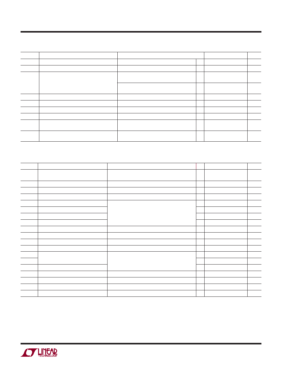
ELECTRICAL CHARACTERISTICS
Note 1: Stresses beyond those listed under Absolute Maximum Ratings
may cause permanent damage to the device. Exposure to any Absolute
Maximum Rating condition for extended periods may affect device
reliability and lifetime.
Note 2: All currents into device pins are positive; all currents out ot device
pins are negative. All voltages are referenced to device ground unless
otherwise specified.
The l denotes the specifications which apply over the full operating
temperature range, otherwise specifications are at TA = 25°C. VCC = 5V ±5%, unless otherwise noted. (Notes 2 and 3)
SWITCHING CHARACTERISTICS The
l
denotes the specifications which apply over the full operating
temperature range, otherwise specifications are at TA = 25°C. VCC = 5V ±5%, unless otherwise noted. (Notes 2 and 3)
SYMBOL PARAMETER
CONDITIONS
MIN
TYP
MAX
UNITS
ICC
Supply Current
No Load, Pins 2, 3, 4 = 0V or 5V
Outputs Enabled
Outputs Disabled
l
500
300
900
500
μA
IOSD1
Driver Short-Circuit Current, VOUT = HIGH VO = – 7V
l
35
100
250
mA
IOSD2
Driver Short-Circuit Current, VOUT = LOW VO = 10V
l
35
100
250
mA
IOSR
Receiver Short-Circuit Current
0V ≤ VO ≤ VCC
l
7
85
mA
tPLH
Driver Input to Output
RDIFF = 54Ω, CL1 = CL2 = 100pF,
(Figures 3 and 5)
l
10
30
50
ns
tPHL
Driver Input to Output
l
10
30
50
ns
tSKEW
Driver Output to Output
l
5
10
ns
tr, tf
Driver Rise or Fall Time
l
3
15
25
ns
tZH
Driver Enable to Output High
CL = 100pF (Figures 4 and 6) S2 Closed
l
40
70
ns
tZL
Driver Enable to Output Low
CL = 100pF (Figures 4 and 6) S1 Closed
l
40
70
ns
tLZ
Driver Disable Time from Low
CL = 15pF (Figures 4 and 6) S1 Closed
l
40
70
ns
tHZ
Driver Disable Time from High
CL = 15pF (Figures 4 and 6) S2 Closed
l
40
70
ns
tPLH
Receiver Input to Output
RDIFF = 54Ω, CL1 = CL2 = 100pF,
(Figures 3 and 7)
l
30
90
200
ns
tPHL
l
30
90
200
ns
tSKD
|tPLH – tPHL| Differential Receiver Skew
l
13
ns
tZL
Receiver Enable to Output Low
CRL = 15pF (Figures 2 and 8) S1 Closed
l
20
50
ns
tZH
Receiver Enable to Output High
CRL = 15pF (Figures 2 and 8) S2 Closed
l
20
50
ns
tLZ
Receiver Disable from Low
CRL = 15pF (Figures 2 and 8) S1 Closed
l
20
50
ns
tHZ
Receiver Disable from High
CRL = 15pF (Figures 2 and 8) S2 Closed
l
20
50
ns
SYMBOL
PARAMETER
CONDITIONS
MIN
TYP
MAX
UNITS
VIL
Input Low Voltage
DE, DI, RE
l
0.8
V
IIN1
Input Current
DE, DI, RE
l
±2
μA
IIN2
Input Current (A, B)
DE = 0, VCC = 0V or 5.25V
VIN = 12V
C-, I-Grade
VIN = –7V
l
1
–0.8
mA
M-Grade
VIN = 12V
VIN = –7V
l
2
–1.6
mA
VTH
Differential Input Threshold Voltage for Receiver –7V ≤ VCM ≤ 12V
l
–0.2
0.2
V
ΔVTH
Receiver Input Hysteresis
VCM = 0V
l
70
mV
VOH
Receiver Output High Voltage
IO = –4mA, VID = 200mV
l
3.5
V
VOL
Receiver Output Low Voltage
IO = 4mA, VID = –200mV
l
0.4
V
IOZR
Three-State (High Impedance) Output Current
at Receiver
VCC = Max, 0.4V ≤ VO ≤ 2.4V
l
±1
μA
RIN
Receiver Input Resistance
–7V ≤ VCM ≤ 12V (C-, I-Grade)
(M-Grade)
l
12
6
kΩ
Note 3: All typicals are given for VCC = 5V and TA = 25°C.
Note 4: The LTC485 is guaranteed by design to be functional over a supply
voltage range of 5V ±10%. Data sheet parameters are guaranteed over the
tested supply voltage range of 5V ±5%.
相关PDF资料 |
PDF描述 |
|---|---|
| LTC487IN#PBF | IC DVR RS485 LOW PWR QUAD 16-DIP |
| LTC488ISW#TRPBF | IC LINE RCVR RS485 QUAD 16-SOIC |
| LTC6601CUF-2#PBF | IC DRVR FILTER/ADC LN 20-QFN |
| LTC6601IUF-1#TRPBF | IC DRVR FILTER/ADC LN 20-QFN |
| LTC6602IUF#PBF | IC FILTER BANDPASS/LOWPASS 24QFN |
相关代理商/技术参数 |
参数描述 |
|---|---|
| LTC485MJ8 | 制造商:Linear Technology 功能描述:MS-Interface, Low Power RS485 Interface Transceiver |
| LTC486CN | 功能描述:IC DVR RS485 LOW PWR QUAD 16-DIP RoHS:否 类别:集成电路 (IC) >> 接口 - 驱动器,接收器,收发器 系列:- 标准包装:27 系列:- 类型:收发器 驱动器/接收器数:3/3 规程:RS232,RS485 电源电压:4.75 V ~ 5.25 V 安装类型:表面贴装 封装/外壳:28-SOIC(0.295",7.50mm 宽) 供应商设备封装:28-SOIC 包装:管件 |
| LTC486CN#PBF | 功能描述:IC DVR RS485 LOW PWR QUAD 16-DIP RoHS:是 类别:集成电路 (IC) >> 接口 - 驱动器,接收器,收发器 系列:- 产品培训模块:RS-232 & USB Transceiver 标准包装:2,000 系列:- 类型:收发器 驱动器/接收器数:1/1 规程:RS232 电源电压:3 V ~ 5.5 V 安装类型:表面贴装 封装/外壳:16-SSOP(0.209",5.30mm 宽) 供应商设备封装:16-SSOP 包装:带卷 (TR) 其它名称:296-19849-2 |
| LTC486CNPBF | 制造商:Linear Technology 功能描述:LTC486CNPBF |
| LTC486CSW | 功能描述:IC DVR RS485 LOW PWR QUAD 16SOIC RoHS:否 类别:集成电路 (IC) >> 接口 - 驱动器,接收器,收发器 系列:- 标准包装:27 系列:- 类型:收发器 驱动器/接收器数:3/3 规程:RS232,RS485 电源电压:4.75 V ~ 5.25 V 安装类型:表面贴装 封装/外壳:28-SOIC(0.295",7.50mm 宽) 供应商设备封装:28-SOIC 包装:管件 |
发布紧急采购,3分钟左右您将得到回复。