- 您现在的位置:买卖IC网 > PDF目录383291 > LTC486CN (LINEAR TECHNOLOGY CORP) Quad Low Power RS485 Driver PDF资料下载
参数资料
| 型号: | LTC486CN |
| 厂商: | LINEAR TECHNOLOGY CORP |
| 元件分类: | 通用总线功能 |
| 英文描述: | Quad Low Power RS485 Driver |
| 中文描述: | QUAD LINE DRIVER, PDIP16 |
| 封装: | PLASTIC, DIP-16 |
| 文件页数: | 7/8页 |
| 文件大小: | 227K |
| 代理商: | LTC486CN |
7
LTC486
U
S
A
O
PPLICATI
U
U
Information furnished by Linear Technology Corporation is believed to be accurate and reliable.
However, no responsibility is assumed for its use. Linear Technology Corporation makes no represen-
tation that the interconnection of its circuits as described herein will not infringe on existing patent rights.
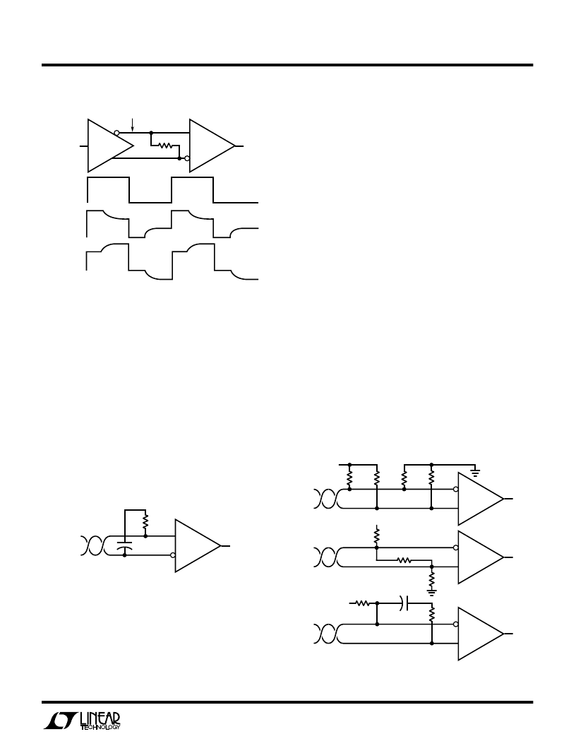
represents an electrical one-tenth wavelength. The value
of the coupling capacitor should therefore be set at 16.3pF
per foot of cable length for 120
cables. With the coupling
capacitors in place, power is consumed only on the signal
edges, not when the driver output is idling at a 1 or 0 state.
A 100nF capacitor is adequate for lines up to 4000 feet in
length. Be aware that the power savings start to decrease
once the data rate surpasses 1/(120
×
C).
Receiver Open-Circuit Fail-Safe
Some data encoding schemes require that the output of
the receiver maintains a known state (usually a logic 1)
when the data is finished transmitting and all drivers on
the line are forced into three-state. All LTC RS485
receivers have a fail-safe feature which guarantees the
output to be in a logic 1 state when the receiver inputs
are left floating (open-circuit). However, when the cable
is terminated with 120
, the differential inputs to the
receiver are shorted together, not left floating.
If the receiver output must be forced to a known state,
the circuits of Figure 11 can be used.
The termination resistors are used to generate a DC bias
which forces the receiver output to a known state, in this
case a logic 0. The first method consumes about
208mW and the second about 8mW. The lowest power
Figure 10. AC Coupled Termination
Rt
DRIVER
DX
RECEIVER
RX
Rt = 120
Rt = 47
Rt = 470
LTC486 TA10
PROBE HERE
Figure 9. Termination Effects
the signal reflects in phase and increases the amplitude at
the driver output. An input frequency of 30kHz is adequate
for tests out to 4000 ft. of cable.
AC Cable Termination
Cable termination resistors are necessary to prevent un-
wanted reflections, but they consume power. The typical
differential output voltage of the driver is 2V when the cable
is terminated with two 120
resistors. When no data is
being sent 33mA of DC current flows in the cable . This DC
current is about 220 times greater than the supply current
of the LTC486. One way to eliminate the unwanted current
is by AC coupling the termination resistors as shown in
Figure 10.
LTC486 TA11
C = LINE LENGTH (FT)
×
16.3pF
120
RECEIVER
RX
C
LTC486 TA12
140
RECEIVER
RX
5V
1.5k
RECEIVER
RX
5V
110
130
110
130
120
RECEIVER
RX
C
5V
100k
1.5k
Figure 11. Forcing “0” When All Dirvers Are Off
The coupling capacitor allows high frequency energy to
flow to the termination, but blocks DC and low frequen-
cies. The dividing line between high and low frequency
depends on the length of the cable. The coupling capacitor
must pass frequencies above the point where the line
相关PDF资料 |
PDF描述 |
|---|---|
| LTC486CS | Quad Low Power RS485 Driver |
| LTC486I | Quad Low Power RS485 Driver |
| LTC486IN | Quad Low Power RS485 Driver |
| LTC486IS | Quad Low Power RS485 Driver |
| M141331FAP | Thick Film Low Profile SIP Conformal Coated Resistor Networks |
相关代理商/技术参数 |
参数描述 |
|---|---|
| LTC486CN#PBF | 功能描述:IC DVR RS485 LOW PWR QUAD 16-DIP RoHS:是 类别:集成电路 (IC) >> 接口 - 驱动器,接收器,收发器 系列:- 产品培训模块:RS-232 & USB Transceiver 标准包装:2,000 系列:- 类型:收发器 驱动器/接收器数:1/1 规程:RS232 电源电压:3 V ~ 5.5 V 安装类型:表面贴装 封装/外壳:16-SSOP(0.209",5.30mm 宽) 供应商设备封装:16-SSOP 包装:带卷 (TR) 其它名称:296-19849-2 |
| LTC486CNPBF | 制造商:Linear Technology 功能描述:LTC486CNPBF |
| LTC486CSW | 功能描述:IC DVR RS485 LOW PWR QUAD 16SOIC RoHS:否 类别:集成电路 (IC) >> 接口 - 驱动器,接收器,收发器 系列:- 标准包装:27 系列:- 类型:收发器 驱动器/接收器数:3/3 规程:RS232,RS485 电源电压:4.75 V ~ 5.25 V 安装类型:表面贴装 封装/外壳:28-SOIC(0.295",7.50mm 宽) 供应商设备封装:28-SOIC 包装:管件 |
| LTC486CSW#PBF | 功能描述:IC DVR RS485 LOW PWR QUAD 16SOIC RoHS:是 类别:集成电路 (IC) >> 接口 - 驱动器,接收器,收发器 系列:- 产品培训模块:RS-232 & USB Transceiver 标准包装:2,000 系列:- 类型:收发器 驱动器/接收器数:1/1 规程:RS232 电源电压:3 V ~ 5.5 V 安装类型:表面贴装 封装/外壳:16-SSOP(0.209",5.30mm 宽) 供应商设备封装:16-SSOP 包装:带卷 (TR) 其它名称:296-19849-2 |
| LTC486CSW#PBF | 制造商:Linear Technology 功能描述:IC RS-485 BUS/LINE DRIVER 5V SOL-16 |
发布紧急采购,3分钟左右您将得到回复。