- 您现在的位置:买卖IC网 > PDF目录39438 > LX7203-22ISMT (MICROSEMI CORP-ANALOG MIXED SIGNAL GROUP) 1 FUNCTIONS, DATA LINE FILTER PDF资料下载
参数资料
| 型号: | LX7203-22ISMT |
| 厂商: | MICROSEMI CORP-ANALOG MIXED SIGNAL GROUP |
| 元件分类: | 数据传输滤波器 |
| 英文描述: | 1 FUNCTIONS, DATA LINE FILTER |
| 文件页数: | 3/7页 |
| 文件大小: | 307K |
| 代理商: | LX7203-22ISMT |
LX7203-xx
PRODUCTION DATA SHEET
Microsemi
Integrated Products Division
11861 Western Avenue, Garden Grove, CA. 92841, 714-898-8121, Fax: 714-893-2570
Page 3
WWW
.Microse
m
i
.CO
M
EMI Filter & ESD Protection for Up Stream USB
Ports
Copyright
2002
Rev. 1.0a, 2002-10-22
I N T E GR A T ED
PRO DUC T S
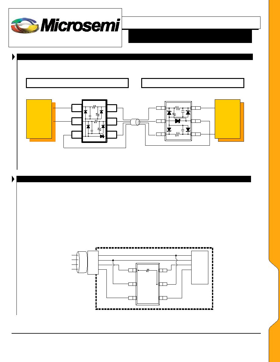
APPLICATION CIRCUITS
USB
Transceiver
Host or Hub (downstream port)
Peripheral (upstream port)
USB
Transceiver
1
6
5
4
3
2
V
BUS
GND
C
R
S
R
PD
R
PD
R
S
C
16
5
4
3
2
V
BUS
GND
R
S
C
R
S
C
R
PU
LX7203
LX7201
Figure 1 –
Typical Application
APPLICATION INFORMATION
The LX7203 meets the requirements of the USB v1.1
specification for device termination, EMI filtering and ESD
protection. The RS resistor provides the proper signal
termination; the CEDGE capacitor controls the signal rise and
fall slew; the TVS diodes protect the IC from ESD damage;
and the total capacitance and resistance creates a low pass
filter eliminating the high frequency energy from the circuit.
The LX7203 can configure the upstream port for either Full-
Speed or Low-Speed operation. The figures below show the
proper connection in accordance with the USB v1.1
specification.
FULL SPEED DEVICE (FIGURE 2)
The USB specification offers a 12 Mbps data transfer
rate known as Full-Speed which requires a 1.5 k pull-up
resistor to be connected to the D+ line. Slew rate control
is accomplished with CEDGE attached to the transceiver
before the RS.
Voltage Supply (Vbus) is connected to Pin 5
Ground is connected to Pin 2
D+ from the connector is routed to Pin 1 (1.5 k pull-up
resistor) and Pin 6 to the D+ line of the USB
Transceiver
D- from the connector is routed to Pin 3 and Pin 4 to
the D- line of the USB Transceiver
cable
Host
USB
Transceiver
GND
D+
D-
V
BUS
Peripheral
USB
Transceiver
GND
D+
D-
V
BUS
R
PU
1
6
5
4
3
2
V
BUS
D
IN
from connector
D
OUT
to IC
GND
D
IN
from connector
D
OUT
to IC
LX7203
Figure 2 –
Connection for Full Speed Operation
AA
PP
LL
IICC
AA
TT
IIOO
NN
SS
相关PDF资料 |
PDF描述 |
|---|---|
| LX7205ISP | 2 FUNCTIONS, 5 V, DATA LINE FILTER |
| LX7207ISP | 1 FUNCTIONS, DATA LINE FILTER |
| LX7207ISP | 10 FUNCTIONS, DATA LINE FILTER |
| LX7207SPT | 1 FUNCTIONS, DATA LINE FILTER |
| LXM1612-05 | SPECIALTY ANALOG CIRCUIT, XMA |
相关代理商/技术参数 |
参数描述 |
|---|---|
| LX7203-XX | 制造商:MICROSEMI 制造商全称:Microsemi Corporation 功能描述:EMI Filter & ESD Protection for Up Stream USB Ports |
| LX-7204T-002AC | 制造商:MRV 制造商全称:MRV 功能描述:7304/7204 Sensor Manager |
| LX-7204T-012DC | 制造商:MRV 制造商全称:MRV 功能描述:7304/7204 Sensor Manager |
| LX7206 | 制造商:MICROSEMI 制造商全称:Microsemi Corporation 功能描述:Integrated EMI Filter & ESD Protection for Earpiece Speaker & Microphone Ports |
| LX723 | 制造商:POLYFET 制造商全称:Polyfet RF Devices 功能描述:SILICON GATE ENHANCEMENT MODE RF POWER LDMOS TRANSISTOR |
发布紧急采购,3分钟左右您将得到回复。