- 您现在的位置:买卖IC网 > PDF目录39438 > LXM1621-02 SPECIALTY ANALOG CIRCUIT, XMA PDF资料下载
参数资料
| 型号: | LXM1621-02 |
| 元件分类: | 模拟信号调理 |
| 英文描述: | SPECIALTY ANALOG CIRCUIT, XMA |
| 文件页数: | 5/8页 |
| 文件大小: | 206K |
| 代理商: | LXM1621-02 |
DIGITAL DIMMING DUAL LAMP CCFL INVERTER MODULE
LXM1621-xx
PRODUCT DA T ABOOK 1996/1997
5
Copyright 1999
Rev. 0.5 11/99
P RELIMINAR Y D ATA S HEET
P A TENT P ENDING
RangeMAXTM
CONNECTOR SCHEMA TIC
CN2
CN3
CN1
4
3
2
1
2
3
CN4
N.C.
3
2
1
CN5
1
2
3
4
N.C.
Inverter
Output
1
Inverter
Output
2
81
V
HI2
V
HI1
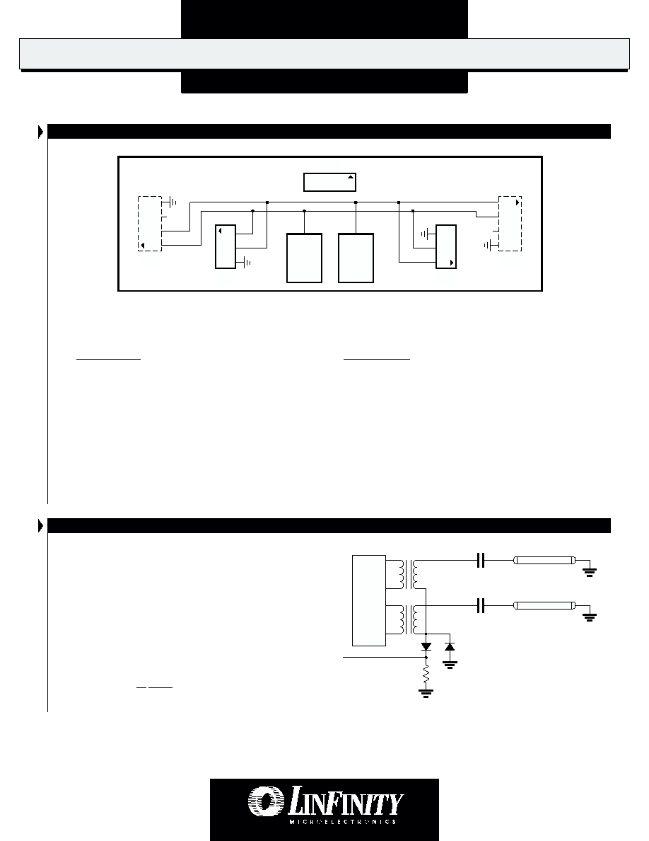
FIGURE 2 — LXM1621-01 Connector Schematic
Note: CN2 and CN3 (shown with dashed lines) are located on the opposite side of the PCB from CN1, CN4
and CN5. Their pin numbers are shown as viewed looking through the printed circuit board.
Connectors:
Mates With:
CN1 = MOLEX 53261-0890
Pins: 50079-8100*, Housing: 51021-0800
* Loose (-8000, Chain) Recommended #26 AWG wiring
CN2, CN3 = JST SM04(4.0)B-BHS-1-TB
JST BHR-04VS-1
CN4, CN5 = JST SM03(4.0)B-BHS-1-TB
JST BHR-03VS-1
Connection Rules
1. Always install two (2) lamps. Operating with only one lamp may overdrive lamp current at maximum brightness settings.
2. Verify lamp wiring before connecting lamps to the inverter module. Connecting both lamps to one of the two inverter output circuits
will result in reduced brightness. The LXM1621-01 module connectors are wired per industry standard. The lamp hot wires (high
voltage wires) are always on pin 1 or 2, and the cold wire (low voltage wire) is always on pin 3 or 4.
F AILSAFE FEATURE FOR MUL TIPLE LAMP OPERATIONS
Our multi-output inverters are designed to keep your application
operating at near normal brightness in the event that a lamp fails.
This allows the display to remain "on-line" until lamp replacement
is convenient.
Linfinity "pairs" the lamps so that if one lamp in the pair breaks,
most of its current is added to the good lamp. CCFLs will respond
with more brightness for a period of time. Operating time in this
mode will be a function of the lamps age but should be typically
in the order of hundreds of hours.
This operating characteristic can provide adequate display
performance for a limited, but useful period of time. Shortening
of the lamp life in this mode is typically not a concern as it is
recommended that all lamps in a display be replaced at the same
time.
FIGURE 3 — Dual Output Stage
I
S
Lamps
相关PDF资料 |
PDF描述 |
|---|---|
| LXM1640-01 | SPECIALTY ANALOG CIRCUIT, XMA26 |
| LY503ALH | SPECIALTY ANALOG CIRCUIT, PBGA16 |
| LY503ALHTR | SPECIALTY ANALOG CIRCUIT, PBGA16 |
| LY550ALH | SPECIALTY ANALOG CIRCUIT, PBGA16 |
| LZ2131J | SPECIALTY ANALOG CIRCUIT, CDIP20 |
相关代理商/技术参数 |
参数描述 |
|---|---|
| LXM1621-03 | 功能描述:MOD INVERTER CCFL DIM DUAL 6.5MA RoHS:否 类别:光电元件 >> 反相器 系列:LXM1621 标准包装:100 系列:- 输入电压:6.0V 输出:900V 类型:用于 CCFL 和 UV 灯的逆变器 尺寸/尺寸:2.34" L x 0.35" W x 0.35" H(59.5mm x 9mm x 8.9mm) 安装类型:底座安装 |
| LXM1621-04 | 功能描述:MOD INVERTER CCFL DIM DUAL 5MA RoHS:否 类别:光电元件 >> 反相器 系列:LXM1621 标准包装:100 系列:- 输入电压:6.0V 输出:900V 类型:用于 CCFL 和 UV 灯的逆变器 尺寸/尺寸:2.34" L x 0.35" W x 0.35" H(59.5mm x 9mm x 8.9mm) 安装类型:底座安装 |
| LXM1621-XX | 制造商:MICROSEMI 制造商全称:Microsemi Corporation 功能描述:DIGITAL DIMMING DUAL LAMP CCFL INVERTER MODULE |
| LXM1622-05-01 | 制造商:未知厂家 制造商全称:未知厂家 功能描述:CCFL Inverter Module - Dual Lamp |
| LXM1622-05-02 | 制造商:未知厂家 制造商全称:未知厂家 功能描述:CCFL Inverter Module - Dual Lamp |
发布紧急采购,3分钟左右您将得到回复。