- 您现在的位置:买卖IC网 > PDF目录262644 > LYT770-JM (INFINEON TECHNOLOGIES AG) SINGLE COLOR LED, YELLOW, 2.4 mm PDF资料下载
参数资料
| 型号: | LYT770-JM |
| 厂商: | INFINEON TECHNOLOGIES AG |
| 元件分类: | LED |
| 英文描述: | SINGLE COLOR LED, YELLOW, 2.4 mm |
| 文件页数: | 17/27页 |
| 文件大小: | 318K |
| 代理商: | LYT770-JM |
第1页第2页第3页第4页第5页第6页第7页第8页第9页第10页第11页第12页第13页第14页第15页第16页当前第17页第18页第19页第20页第21页第22页第23页第24页第25页第26页第27页
Infineon Technologies AG
69
1999-05-01
Lumineszenzdioden
Light Emitting Diodes
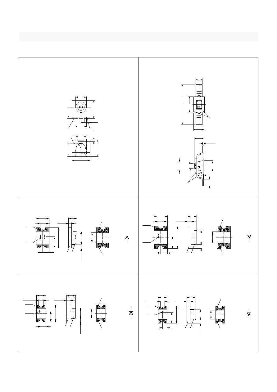
Figure 21
LSY A676, L** A671
Figure 22
L* M770, L* M776, L* M779
Figure 23
L* R971, L* R976
Figure 24
LH R974
Figure 25
L* Q971, L* Q976
Figure 26
LH Q974
Mabilder in inch (mm)
Outline drawings in inch (mm)
GPLY6950
spacing
(R1)
1
Package marking
0.114
(2.9)
0.150 (3.8)
0.165 (4.2)
0.055 (1.4)
0.150
(3.8)
0.012
(0.3)
2
0.110
(2.8)
0.094
(2.4)
0.100 (2.54)
0.035 (0.9)
0.043 (1.1)
0.165
(4.2)
0.150
(3.8)
0.094 (2.4)
0.134
(3.4)
.082 (2.1)
.075 (1.9)
.039 (1.0)
.031 (0.8)
.059 (1.5)
.051 (1.3)
.043 (1.1)
.007 (.18)
.004 (.12)
cathode marking
cathode
marking
0–.004 (0–0.1)
.027 (0.7)
min.
.055 x .031 typ.
(1.4 x 0.8) typ.
.023 (0.6)
.019 (0.5)
.053 (1.35)
.049 (1.25)
.212 (5.4)
.197 (5.0)
mark
LED die
Cathode
0.020 (0.5)
0.049 (1.25)
0.043
(1.1)
0.079
(2.0)
0.025 (0.625)
0.031 (0.8)
0.012 (0.3)
Resin
P.C. board
0.014
(0.35)
0.051
(1.3)
0.039
(1.0)
Soldering terminal
Polarity
may flow in x, y direction)
Soldering terminal
(Size: 0.016 (0.4) x 0.045 (1.15)
GEOY6024
Tolerance ±0.1 mm unless otherwise noted
mark
LED die
Anode
0.020 (0.5)
0.049 (1.25)
0.043
(1.1)
0.079
(2.0)
0.025 (0.625)
0.031 (0.8)
0.012 (0.3)
Resin
P.C. board
0.014
(0.35)
0.051
(1.3)
0.039
(1.0)
Soldering terminal
Polarity
may flow in x, y direction)
Soldering terminal
(Size: 0.016 (0.4) x 0.045 (1.15)
GEOY6026
Tolerance ±0.1 mm unless otherwise noted
0.016 (0.4)
0.031 (0.8)
mark
Cathode
LED die
0.016 (0.4)
0.039
(1.0)
0.063
(1.6)
0.012 (0.3)
0.031 (0.8)
P.C. board Resin
0.012
(0.3)
0.031
(0.8)
Soldering terminal
Polarity
may flow in x, y direction)
Soldering terminal
(size: 0.012 (0.3) x 0.024 (0.6)
GEOY6989
Tolerance ±0.1 mm unless otherwise noted
0.039
(1.0)
0.016 (0.4)
0.031 (0.8)
mark
Anode
LED die
0.016 (0.4)
0.039
(1.0)
0.063
(1.6)
0.012 (0.3)
0.031 (0.8)
P.C. board Resin
0.012
(0.3)
0.031
(0.8)
Soldering terminal
Polarity
may flow in x, y direction)
Soldering terminal
(size: 0.012 (0.3) x 0.024 (0.6)
GEOY6027
Tolerance ±0.1 mm unless otherwise noted
0.039
(1.0)
相关PDF资料 |
PDF描述 |
|---|---|
| L575CO3K-36VF-S | SINGLE COLOR DISPLAY CLUSTER, ULTRA BRIGHT ORANGE, 14.6 mm |
| LD80C51XXX-1 | 8-BIT, MROM, 16 MHz, MICROCONTROLLER, CDIP40 |
| LS80C31-1 | 8-BIT, 16 MHz, MICROCONTROLLER, PQCC44 |
| LV80C51FXXX-1 | 8-BIT, MROM, 16 MHz, MICROCONTROLLER, PQFP44 |
| LV83C154XXX-L | 8-BIT, MROM, 6 MHz, MICROCONTROLLER, PQFP44 |
相关代理商/技术参数 |
参数描述 |
|---|---|
| LYT770-K | 制造商:INFINEON 制造商全称:Infineon Technologies AG 功能描述:TOPLED RG |
| LYT770K1L21 | 制造商:OSRAM 功能描述:* |
| LYT770-L | 制造商:INFINEON 制造商全称:Infineon Technologies AG 功能描述:TOPLED RG |
| LYT776-PS | 制造商:INFINEON 制造商全称:Infineon Technologies AG 功能描述:Hyper TOPLED RG Hyper-Bright LED |
| LYT776-Q | 制造商:INFINEON 制造商全称:Infineon Technologies AG 功能描述:Hyper TOPLED RG Hyper-Bright LED |
发布紧急采购,3分钟左右您将得到回复。