- 您现在的位置:买卖IC网 > PDF目录262797 > M27C512-10XC1F (意法半导体) 512 Kbit 64Kb x8 UV EPROM and OTP EPROM PDF资料下载
参数资料
| 型号: | M27C512-10XC1F |
| 厂商: | 意法半导体 |
| 英文描述: | 512 Kbit 64Kb x8 UV EPROM and OTP EPROM |
| 中文描述: | 512千位64Kb的x8紫外线存储器和OTP存储器 |
| 文件页数: | 20/22页 |
| 文件大小: | 403K |
| 代理商: | M27C512-10XC1F |
7/22
M27C512
tion, a 4.7F bulk electrolytic capacitor should be
used between VCC and VSS for every eight devic-
es. The bulk capacitor should be located near the
power supply connection point.The purpose of the
bulk capacitor is to overcome the voltage drop
caused by the inductive effects of PCB traces.
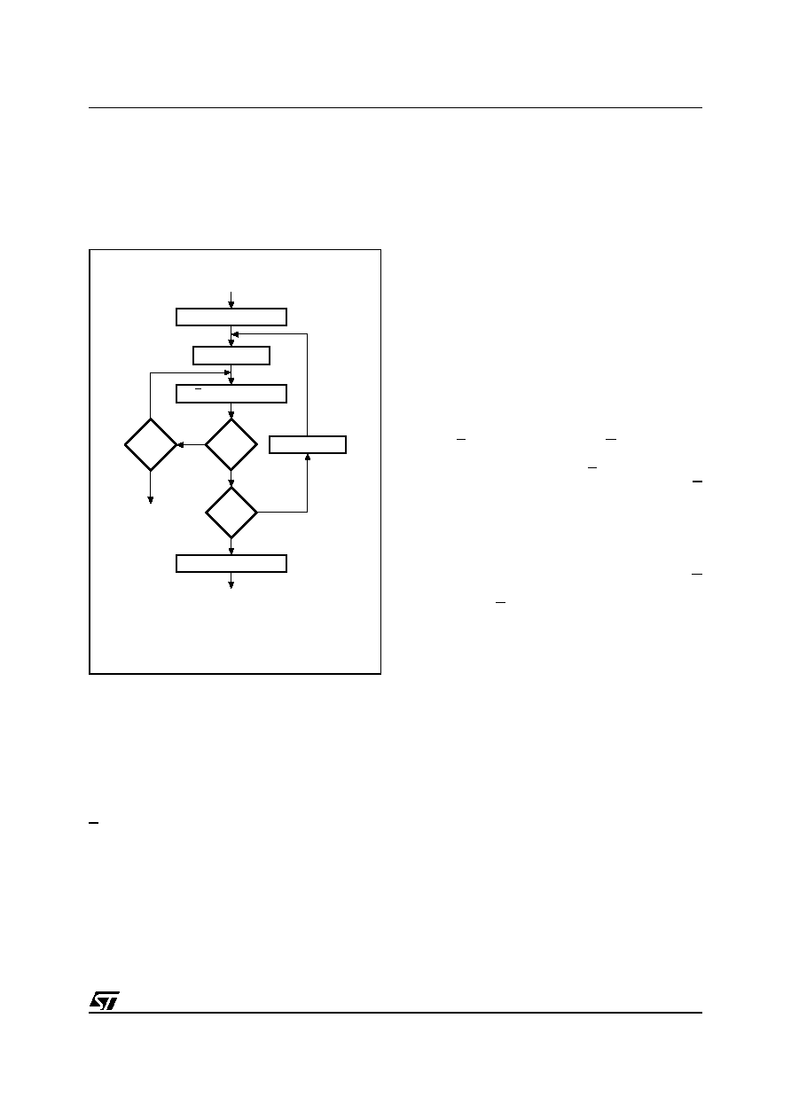
Figure 6. Programming Flowchart
Programming
When delivered (and after each erasure for UV
EPROM), all bits of the M27C512 are in the '1'
state. Data is introduced by selectively program-
ming '0's into the desired bit locations. Although
only '0's will be programmed, both '1's and '0's can
be present in the data word. The only way to
change a '0' to a '1' is by die exposure to ultraviolet
light (UV EPROM). The M27C512 is in the pro-
gramming mode when VPP input is at 12.75V and
E is pulsed to VIL. The data to be programmed is
applied to 8 bits in parallel to the data output pins.
The levels required for the address and data in-
puts are TTL. VCC is specified to be 6.25V ±
0.25V. The M27C512 can use PRESTO IIB Pro-
gramming Algorithm that drastically reduces the
programming time (typically less than 6 seconds).
Nevertheless to achieve compatibility with all pro-
gramming equipments, PRESTO Programming
Algorithm can be used as well.
PRESTO IIB Programming Algorithm
PRESTO IIB Programming Algorithm allows the
whole array to be programmed with a guaranteed
margin, in a typical time of 6.5 seconds. This can
be achieved with STMicroelectronics M27C512
due to several design innovations described in the
M27C512 datasheet to improve programming effi-
ciency and to provide adequate margin for reliabil-
ity. Before starting the programming the internal
MARGIN MODE circuit is set in order to guarantee
that each cell is programmed with enough margin.
Then a sequence of 100s program pulses are ap-
plied to each byte until a correct verify occurs. No
overprogram pulses are applied since the verify in
MARGIN MODE provides the necessary margin.
Program Inhibit
Programming of multiple M27C512s in parallel
with different data is also easily accomplished. Ex-
cept for E, all like inputs including GVPP of the par-
allel M27C512 may be common. A TTL low level
pulse applied to a M27C512's E input, with VPP at
12.75V, will program that M27C512. A high level E
input inhibits the other M27C512s from being pro-
grammed.
Program Verify
A verify (read) should be performed on the pro-
grammed bits to determine that they were correct-
ly programmed. The verify is accomplished with G
at VIL. Data should be verified with tELQV after the
falling edge of E.
Electronic Signature
The Electronic Signature (ES) mode allows the
reading out of a binary code from an EPROM that
will identify its manufacturer and type. This mode
is intended for use by programming equipment to
automatically match the device to be programmed
with its corresponding programming algorithm.
The ES mode is functional in the 25°C ± 5°C am-
bient temperature range that is required when pro-
gramming the M27C512. To activate the ES
mode, the programming equipment must force
11.5V to 12.5V on address line A9 of the
M27C512. Two identifier bytes may then be se-
quenced from the device outputs by toggling ad-
dress line A0 from VIL to VIH. All other address
lines must be held at VIL during Electronic Signa-
ture mode. Byte 0 (A0 = VIL) represents the man-
ufacturer code and byte 1 (A0 = VIH) the device
identifier
code.
For
the
STMicroelectronics
M27C512, these two identifier bytes are given in
Table 3. and can be read-out on outputs Q7 to Q0.
AI00738B
n = 0
Last
Addr
VERIFY
E = 100
s Pulse
++n
= 25
++ Addr
VCC = 6.25V, VPP = 12.75V
FAIL
CHECK ALL BYTES
1st: VCC = 6V
2nd: VCC = 4.2V
YES
NO
YES
NO
YES
NO
SET MARGIN MODE
RESET MARGIN MODE
相关PDF资料 |
PDF描述 |
|---|---|
| M27C512-20XC1F | 512 Kbit 64Kb x8 UV EPROM and OTP EPROM |
| MSU2031 | 8 - Bit Microcontroller |
| MSU2031C16 | low working voltage 16 MHz ROM less MCU |
| MSU2031C25 | low working voltage 16 MHz ROM less MCU |
| MSU2031S16 | Datamate Hand Crimp Tool |
相关代理商/技术参数 |
参数描述 |
|---|---|
| M27C51212B1 | 制造商:STME 功能描述: 制造商:STMicroelectronics 功能描述: |
| M27C512-12B1 | 功能描述:可擦除可编程ROM 512K (64Kx8) 120ns RoHS:否 制造商:Maxim Integrated 类型: 存储容量:1024 bit 组织:1 K x 1 接口类型: 工作电流:5 uA 编程电压: 工作电源电压:2.8 V to 6 V 最大工作温度:+ 85 C 安装风格:Through Hole 封装 / 箱体:TO-92 |
| M27C512-12C1 | 功能描述:可擦除可编程ROM 512K (64Kx8) 120ns RoHS:否 制造商:Maxim Integrated 类型: 存储容量:1024 bit 组织:1 K x 1 接口类型: 工作电流:5 uA 编程电压: 工作电源电压:2.8 V to 6 V 最大工作温度:+ 85 C 安装风格:Through Hole 封装 / 箱体:TO-92 |
| M27C512-12C1E | 制造商:STMicroelectronics 功能描述:EPROM OTP 512KBIT 64KX8 120NS 32PLCC - Bulk |
| M27C512-12C6 | 功能描述:可擦除可编程ROM 512K (64Kx8) 120ns RoHS:否 制造商:Maxim Integrated 类型: 存储容量:1024 bit 组织:1 K x 1 接口类型: 工作电流:5 uA 编程电压: 工作电源电压:2.8 V to 6 V 最大工作温度:+ 85 C 安装风格:Through Hole 封装 / 箱体:TO-92 |
发布紧急采购,3分钟左右您将得到回复。