- 您现在的位置:买卖IC网 > PDF目录359024 > M29F016B90M6T (意法半导体) 16 Mbit 2Mb x8, Uniform Block Single Supply Flash Memory PDF资料下载
参数资料
| 型号: | M29F016B90M6T |
| 厂商: | 意法半导体 |
| 英文描述: | 16 Mbit 2Mb x8, Uniform Block Single Supply Flash Memory |
| 中文描述: | 16兆位的2Mb × 8,统一座单电源闪存 |
| 文件页数: | 5/22页 |
| 文件大小: | 135K |
| 代理商: | M29F016B90M6T |
5/22
M29F016B
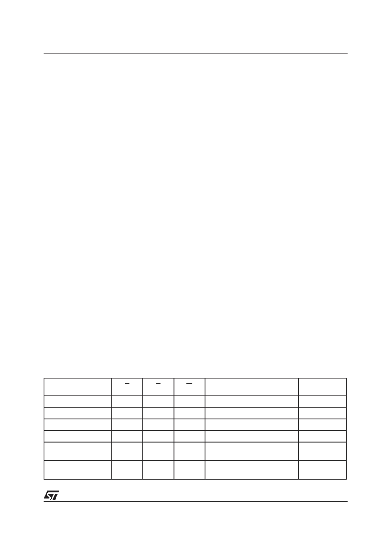
Table 4. Bus Operations
Note: X = V
IL
or V
IH
.
Operation
E
G
W
Address Inputs
Data
Inputs/Outputs
Bus Read
V
IL
V
IL
V
IH
Cell Address
Data Output
Bus Write
V
IL
V
IH
V
IL
Command Address
Data Input
Output Disable
X
V
IH
V
IH
X
Hi-Z
Standby
V
IH
X
X
X
Hi-Z
Read Manufacturer
Code
V
IL
V
IL
V
IH
A0 = V
IL
, A1 = V
IL
, A9 = V
ID
,
Others V
IL
or V
IH
20h
Read Device Code
V
IL
V
IL
V
IH
A0 = V
IH
, A1 = V
IL
, A9 = V
ID
,
Others V
IL
or V
IH
ADh
After a Hardware Reset, Bus Read and Bus Write
operations cannot begin until Ready/Busy be-
comes high-impedance. See Table 14 and Figure
11, Reset/Temporary Unprotect AC Characteris-
tics.
During Program or Erase operations Ready/Busy
is Low, V
OL
. Ready/Busy will remain Low during
Read/Reset commands or Hardware Resets until
the memory is ready to enter Read mode.
The use of an open-drain output allows the Ready/
Busy pins from severalmemories to be connected
to a single pull-up resistor. A Low will then indicate
that one, or more, of the memories is busy.
V
CC
Supply Voltage.
The V
CC
Supply Voltage
supplies the power for all operations (Read, Pro-
gram, Erase etc.).
The Command Interface is disabled when the V
CC
Supply Voltage is less than the Lockout Voltage,
V
LKO
. Thisprevents Bus Write operations from ac-
cidentally damaging the data during power up,
power down and power surges. If the Program/
Erase Controller is programming or erasing during
this time then the operation aborts and the memo-
ry contents being altered will be invalid.
A 0.1
μ
F capacitor should be connected between
the V
CC
Supply Voltage pin and the V
SS
Ground
pin to decouple the current surges from the power
supply. The PCB track widths must be sufficient to
carry the currents required during program and
erase operations, I
CC4
.
V
SS
Ground.
The V
SS
Groundis thereference for
all voltage measurements.
BUS OPERATIONS
There are five standard busoperations that control
the device. These are Bus Read, Bus Write, Out-
put Disable, Standby and Automatic Standby. See
Table 4, Bus Operations, for a summary. Typically
glitches of less than 5ns on Chip Enable or Write
Enable are ignored by the memory and do not af-
fect bus operations.
Bus Read.
Bus Read operations read from the
memory cells, or specific registers in the Com-
mand Interface. A valid Bus Read operation in-
volves setting the desired address on the Address
Inputs, applying a Low signal, V
IL
, to Chip Enable
and Output Enable and keeping Write Enable
High, V
IH
. The Data Inputs/Outputs will output the
value, see Figure 8, Read Mode AC Waveforms,
and Table 11, Read ACCharacteristics, for details
of when the output becomes valid.
Bus Write.
Bus Write operations write to the
Command Interface. A valid Bus Write operation
begins by setting the desired address on the Ad-
dress Inputs. The Address Inputs are latched by
the Command Interface on the falling edge of Chip
Enable or Write Enable, whichever occurs last.
The Data Inputs/Outputs are latched by the Com-
mand Interface on the rising edge of Chip Enable
or WriteEnable, whichever occurs first.OutputEn-
able must remain High, V
IH
, during the whole Bus
Write operation. See Figures 9 and 10, Write AC
Waveforms, and Tables 12 and 13, Write AC
Characteristics, for details of the timing require-
ments.
Output Disable.
The Data Inputs/Outputs are in
the high impedance state when Output Enable is
High, V
IH
.
Standby.
When Chip Enable is High, V
IH
, the
Data Inputs/Outputs pins are placed in the high-
impedance state and the Supply Current is re-
duced to the Standby level.
When Chip Enable is at V
IH
the Supply Current is
reduced to the TTL Standby Supply Current, I
CC2
.
To further reduce the Supply Current to the CMOS
Standby Supply Current, I
CC3
, Chip Enableshould
be held within V
CC
±
0.2V. For Standby current
levels see Table 10, DC Characteristics.
During program or erase operations the memory
will continue to use the Program/Erase Supply
Current, I
CC4
, for Programor Erase operations un-
til the operation completes.
相关PDF资料 |
PDF描述 |
|---|---|
| M29F016B90N1T | 16 Mbit 2Mb x8, Uniform Block Single Supply Flash Memory |
| M29F016B90N3T | 16 Mbit 2Mb x8, Uniform Block Single Supply Flash Memory |
| M29F016B90N6T | 16 Mbit 2Mb x8, Uniform Block Single Supply Flash Memory |
| M29F016B70M1T | 16 Mbit 2Mb x8, Uniform Block Single Supply Flash Memory |
| M29F016B70M3T | 16 Mbit 2Mb x8, Uniform Block Single Supply Flash Memory |
相关代理商/技术参数 |
参数描述 |
|---|---|
| M29F016B90N1T | 制造商:STMICROELECTRONICS 制造商全称:STMicroelectronics 功能描述:16 Mbit 2Mb x8, Uniform Block Single Supply Flash Memory |
| M29F016B90N3T | 制造商:STMICROELECTRONICS 制造商全称:STMicroelectronics 功能描述:16 Mbit 2Mb x8, Uniform Block Single Supply Flash Memory |
| M29F016B90N6T | 制造商:STMICROELECTRONICS 制造商全称:STMicroelectronics 功能描述:16 Mbit 2Mb x8, Uniform Block Single Supply Flash Memory |
| M29F016D | 制造商:AMD 制造商全称:Advanced Micro Devices 功能描述:16 Megabit (2 M x 8-Bit) CMOS 5.0 Volt-only, Uniform Sector Flash Memory |
| M29F016D_05 | 制造商:STMICROELECTRONICS 制造商全称:STMicroelectronics 功能描述:16 Mbit (2Mb x8, Uniform Block) 5V Supply Flash Memory |
发布紧急采购,3分钟左右您将得到回复。