- 您现在的位置:买卖IC网 > PDF目录45021 > M30625MHP-XXXGP 16-BIT, MROM, 24 MHz, MICROCONTROLLER, PQFP128 PDF资料下载
参数资料
| 型号: | M30625MHP-XXXGP |
| 元件分类: | 微控制器/微处理器 |
| 英文描述: | 16-BIT, MROM, 24 MHz, MICROCONTROLLER, PQFP128 |
| 封装: | 14 X 20 MM, 0.50 MM PITCH, PLASTIC, LQFP-128 |
| 文件页数: | 90/104页 |
| 文件大小: | 1313K |
| 代理商: | M30625MHP-XXXGP |
第1页第2页第3页第4页第5页第6页第7页第8页第9页第10页第11页第12页第13页第14页第15页第16页第17页第18页第19页第20页第21页第22页第23页第24页第25页第26页第27页第28页第29页第30页第31页第32页第33页第34页第35页第36页第37页第38页第39页第40页第41页第42页第43页第44页第45页第46页第47页第48页第49页第50页第51页第52页第53页第54页第55页第56页第57页第58页第59页第60页第61页第62页第63页第64页第65页第66页第67页第68页第69页第70页第71页第72页第73页第74页第75页第76页第77页第78页第79页第80页第81页第82页第83页第84页第85页第86页第87页第88页第89页当前第90页第91页第92页第93页第94页第95页第96页第97页第98页第99页第100页第101页第102页第103页第104页
5. Electrical Characteristics
Rev.2.41
Jan 10, 2006
Page 84 of 96
REJ03B0001-0241
NOTES:
1.
Referenced to VCC1=AVCC=VREF=4.0 to 5.5V, VSS=AVSS=0V at Topr =
40 to 85°C / 40 to 125°C unless otherwise specified.
T version =
40 to 85°C, V version =40 to 125°C
2.
φAD frequency must be 12 MHz or less.
3.
When sample & hold is disabled,
φAD frequency must be 250 kHz or more, in addition to the limitation in Note 2.
When sample & hold is enabled,
φAD frequency must be 1MHz or more, in addition to the limitation in Note 2.
NOTES:
1.
Referenced to VCC1=VREF=4.0 to 5.5V, VSS=AVSS=0V at Topr =
40 to 85°C / 40 to 125°C unless otherwise specified. T
version =
40 to 85°C, V version =40 to 125°C
2.
This applies when using one D/A converter, with the D/A register for the unused D/A converter set to “00h”. The resistor
ladder of the A/D converter is not included. Also, when D/A register contents are not “00h”, the IVREF will flow even if Vref id
disconnected by the A/D control register.
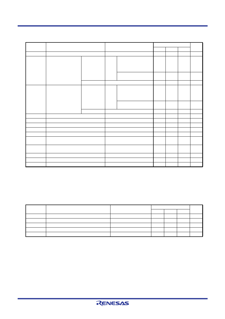
Table 5.51
A/D Conversion Characteristics (1)
Symbol
Parameter
Measuring Condition
Standard
Unit
Min.
Typ.
Max.
Resolution
VREF=VCC1
10
Bits
INL
Integral Non-Linearity
Error
10bit
VREF=
VCC1=
5V
AN0 to AN7 input,
AN0_0 to AN0_7 input,
AN2_0 to AN2_7 input,
ANEX0, ANEX1 input
±3
LSB
External operation amp
connection mode
±7
LSB
8bit
VREF=VCC1=5V
±2
LSB
Absolute Accuracy
10bit
VREF=
VCC1=
5V
AN0 to AN7 input,
AN0_0 to AN0_7 input,
AN2_0 to AN2_7 input,
ANEX0, ANEX1 input
±3
LSB
External operation amp
connection mode
±7
LSB
8bit
VREF=VCC1=5V
±2
LSB
Tolerance Level Impedance
3
k
DNL
Differential Non-Linearity Error
±1
LSB
Offset Error
±3
LSB
Gain Error
±3
LSB
RLADDER
Ladder Resistance
VREF=VCC1
10
40
k
tCONV
10-bit Conversion Time, Sample & Hold
Function Available
VREF=VCC1=5V,
φAD=12MHz
2.75
s
tCONV
8-bit Conversion Time, Sample & Hold
Function Available
VREF=VCC1=5V,
φAD=12MHz
2.33
s
tSAMP
Sampling Time
0.25
s
VREF
Reference Voltage
2.0
VCC1
V
VIA
Analog Input Voltage
0
VREF
V
Table 5.52
D/A Conversion Characteristics (1)
Symbol
Parameter
Measuring Condition
Standard
Unit
Min.
Typ.
Max.
Resolution
8Bits
Absolute Accuracy
1.0
%
tSU
Setup Time
3
s
RO
Output Resistance
4
10
20
k
IVREF
Reference Power Supply Input Current
1.5
mA
相关PDF资料 |
PDF描述 |
|---|---|
| M30626FHPFP | 16-BIT, FLASH, 24 MHz, MICROCONTROLLER, PQFP100 |
| M30626FJPGP | 16-BIT, FLASH, 24 MHz, MICROCONTROLLER, PQFP100 |
| M3062JFHTFP-B7 | 16-BIT, FLASH, 24 MHz, MICROCONTROLLER, PQFP100 |
| M30624FGPGP-U5 | 16-BIT, FLASH, 24 MHz, MICROCONTROLLER, PQFP100 |
| M30626FJPFP-U9 | 16-BIT, FLASH, 24 MHz, MICROCONTROLLER, PQFP100 |
相关代理商/技术参数 |
参数描述 |
|---|---|
| M30625MWP | 制造商:RENESAS 制造商全称:Renesas Technology Corp 功能描述:SINGLE-CHIP 16-BIT CMOS MICROCOMPUTER |
| M30625MWP-XXXGP | 制造商:RENESAS 制造商全称:Renesas Technology Corp 功能描述:SINGLE-CHIP 16-BIT CMOS MICROCOMPUTER |
| M30626FHPFP | 制造商:RENESAS 制造商全称:Renesas Technology Corp 功能描述:SINGLE-CHIP 16-BIT CMOS MICROCOMPUTER |
| M30626FHPFP D5 | 制造商:Renesas Electronics Corporation 功能描述: |
| M30626FHPFP#D3 | 制造商:Renesas Electronics Corporation 功能描述:MCU 16BIT R8C CISC 384KB FLASH 3.3V/5V 100PQFP - Trays |
发布紧急采购,3分钟左右您将得到回复。