- 您现在的位置:买卖IC网 > PDF目录383294 > M34D64-RMN6T (意法半导体) 64 Kbit Serial I2C Bus EEPROM With Hardware Write Control on Top Quarter of Memory PDF资料下载
参数资料
| 型号: | M34D64-RMN6T |
| 厂商: | 意法半导体 |
| 元件分类: | DRAM |
| 英文描述: | 64 Kbit Serial I2C Bus EEPROM With Hardware Write Control on Top Quarter of Memory |
| 中文描述: | 64千位串行I2C总线的EEPROM,带有硬件写控制记忆的热门季 |
| 文件页数: | 5/21页 |
| 文件大小: | 147K |
| 代理商: | M34D64-RMN6T |
5/21
M34D64
DEVICE OPERATION
The device supports the I
2
C protocol. This is
summarized in Figure 6. Any device that sends
data on to the bus is defined to be a transmitter,
and any device that reads the data to be a
receiver. The device that controls the data transfer
is known as the bus master, and the other as the
slave device. A data transfer can only be initiated
by the bus master, which will also provide the
serial clock for synchronization. The M34D64
device is always a slave in all communication.
Start Condition
Start is identified by a falling edge of Serial Data
(SDA) while Serial Clock (SCL) is stable in the
High state. A Start condition must precede any
data transfer command. The device continuously
monitors (except during a Write cycle) Serial Data
(SDA) and Serial Clock (SCL) for a Start condition,
and will not respond unless one is given.
Stop Condition
Stop is identified by a rising edge of Serial Data
(SDA) while Serial Clock (SCL) is stable and
driven High. A Stop condition terminates
communication between the device and the bus
master. A Read command that is followed by
NoAck can be followed by a Stop condition to force
the device into the Stand-by mode. A Stop
condition at the end of a Write command triggers
the internal EEPROM Write cycle.
Acknowledge Bit (ACK)
The acknowledge bit is used to indicate a
successful byte transfer. The bus transmitter,
whether it be bus master or slave device, releases
Serial Data (SDA) after sending eight bits of data.
During the 9
th
clock pulse period, the receiver pulls
Serial Data (SDA) Low to acknowledge the receipt
of the eight data bits.
Data Input
During data input, the device samples Serial Data
(SDA) on the rising edge of Serial Clock (SCL).
For correct device operation, Serial Data (SDA)
must be stable during the rising edge of Serial
Clock (SCL), and the Serial Data (SDA) signal
must change onlywhen Serial Clock (SCL) is
driven Low.
Memory Addressing
To start communication between the bus master
and the slave device, the bus master must initiate
a Start condition. Following this, the bus master
sends the Device Select Code, shown in Table 2
(on Serial Data (SDA), most significant bit first).
The Device Select Code consists of a 4-bit Device
Type Identifier, and a 3-bit Chip Enable “Address”
(E2, E1, E0). To address the memory array, the 4-
bit Device Type Identifier is 1010b.
Up to eight memory devices can be connected on
a single I
2
C bus. Each one is given a unique 3-bit
code on the Chip Enable (E0, E1, E2) inputs.
When the Device Select Code is received on
Serial Data (SDA), the device only responds if the
Chip Enable Address is the same as the value on
the Chip Enable (E0, E1, E2) inputs.
The 8
th
bit is the Read/Write bit (RW). This bit is
set to 1 for Read and 0 for Write operations.
If a match occurs on the Device Select code, the
corresponding device gives an acknowledgment
on Serial Data (SDA) during the 9
th
bit time. If the
device does not match the Device Select code, it
deselects itself from the bus, and goes into Stand-
by mode.
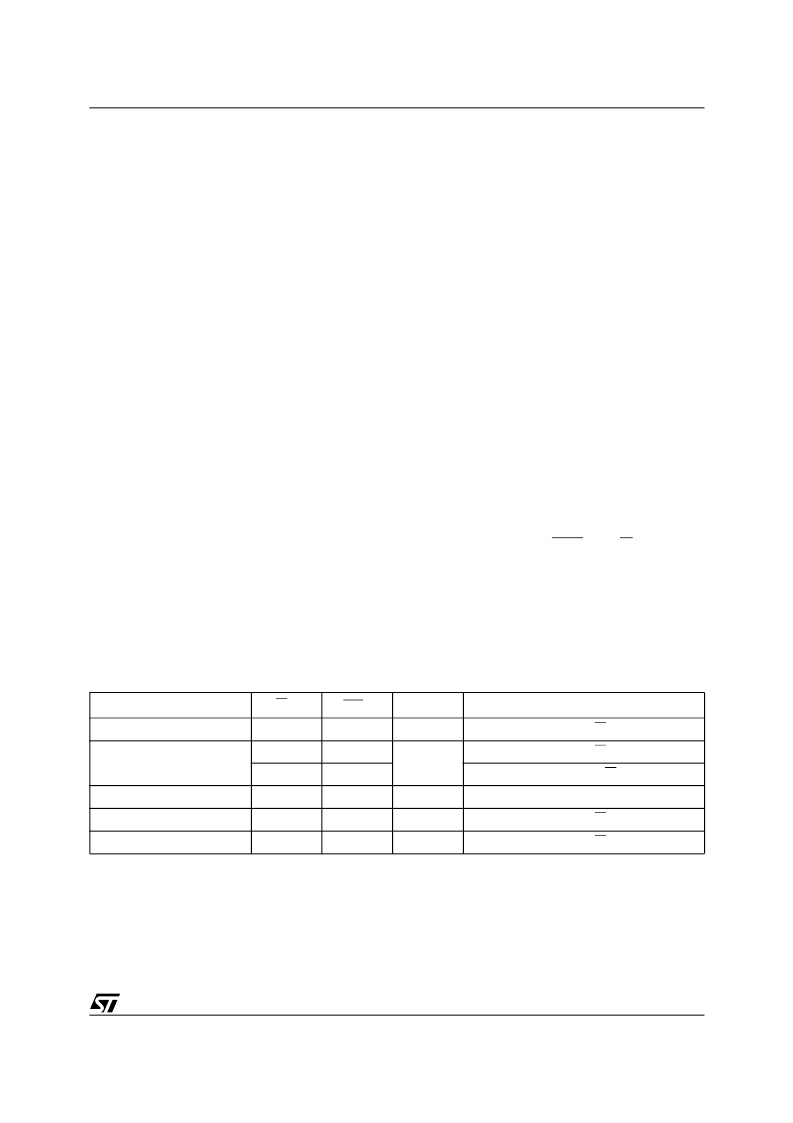
Table 5. Operating Modes
Note: 1. X =
V
IH
or V
IL
.
Mode
RW bit
WC
1
Bytes
Initial Sequence
Current Address Read
1
X
1
START, Device Select, RW = 1
Random Address Read
0
X
1
START, Device Select, RW = 0, Address
1
X
reSTART, Device Select, RW = 1
Sequential Read
1
X
≥
1
Similar to Current or Random Address Read
Byte Write
0
V
IL
1
START, Device Select, RW = 0
Page Write
0
V
IL
≤
32
START, Device Select, RW
= 0
相关PDF资料 |
PDF描述 |
|---|---|
| M34D64-W | 64 Kbit Serial I2C Bus EEPROM With Hardware Write Control on Top Quarter of Memory |
| M34D64-WDW6T | 64 Kbit Serial I2C Bus EEPROM With Hardware Write Control on Top Quarter of Memory |
| M34D64-WMN6T | 64 Kbit Serial I2C Bus EEPROM With Hardware Write Control on Top Quarter of Memory |
| M35062-001SP | SCREEN CHARACTER and PATTERN DISPLAY CONTROLLERS |
| M35062 | SCREEN CHARACTER and PATTERN DISPLAY CONTROLLERS |
相关代理商/技术参数 |
参数描述 |
|---|---|
| M34D64RMNT1 | 制造商:STMICROELECTRONICS 制造商全称:STMicroelectronics 功能描述:64/32 Kbit Serial IC Bus EEPROM With Hardware Write Control on Top Quarter of Memory |
| M34D64RMNT5 | 制造商:STMICROELECTRONICS 制造商全称:STMicroelectronics 功能描述:64/32 Kbit Serial IC Bus EEPROM With Hardware Write Control on Top Quarter of Memory |
| M34D64RMNT6 | 制造商:STMICROELECTRONICS 制造商全称:STMicroelectronics 功能描述:64/32 Kbit Serial IC Bus EEPROM With Hardware Write Control on Top Quarter of Memory |
| M34D64-W | 制造商:STMICROELECTRONICS 制造商全称:STMicroelectronics 功能描述:64 Kbit Serial I2C Bus EEPROM With Hardware Write Control on Top Quarter of Memory |
| M34D64-W_08 | 制造商:STMICROELECTRONICS 制造商全称:STMicroelectronics 功能描述:64 Kbit serial IC bus EEPROM with hardware write control on top quarter of memory |
发布紧急采购,3分钟左右您将得到回复。