- 您现在的位置:买卖IC网 > PDF目录98006 > M37516M6H-XXXKP 8-BIT, MROM, 4 MHz, MICROCONTROLLER, PQFP44 PDF资料下载
参数资料
| 型号: | M37516M6H-XXXKP |
| 元件分类: | 微控制器/微处理器 |
| 英文描述: | 8-BIT, MROM, 4 MHz, MICROCONTROLLER, PQFP44 |
| 封装: | PLASTIC, QFN-44 |
| 文件页数: | 42/63页 |
| 文件大小: | 1124K |
| 代理商: | M37516M6H-XXXKP |
第1页第2页第3页第4页第5页第6页第7页第8页第9页第10页第11页第12页第13页第14页第15页第16页第17页第18页第19页第20页第21页第22页第23页第24页第25页第26页第27页第28页第29页第30页第31页第32页第33页第34页第35页第36页第37页第38页第39页第40页第41页当前第42页第43页第44页第45页第46页第47页第48页第49页第50页第51页第52页第53页第54页第55页第56页第57页第58页第59页第60页第61页第62页第63页
46
SINGLE-CHIP 8-BIT CMOS MICROCOMPUTER
MITSUBISHI MICROCOMPUTERS
7516 Group (Spec.H)
CLOCK GENERATING CIRCUIT
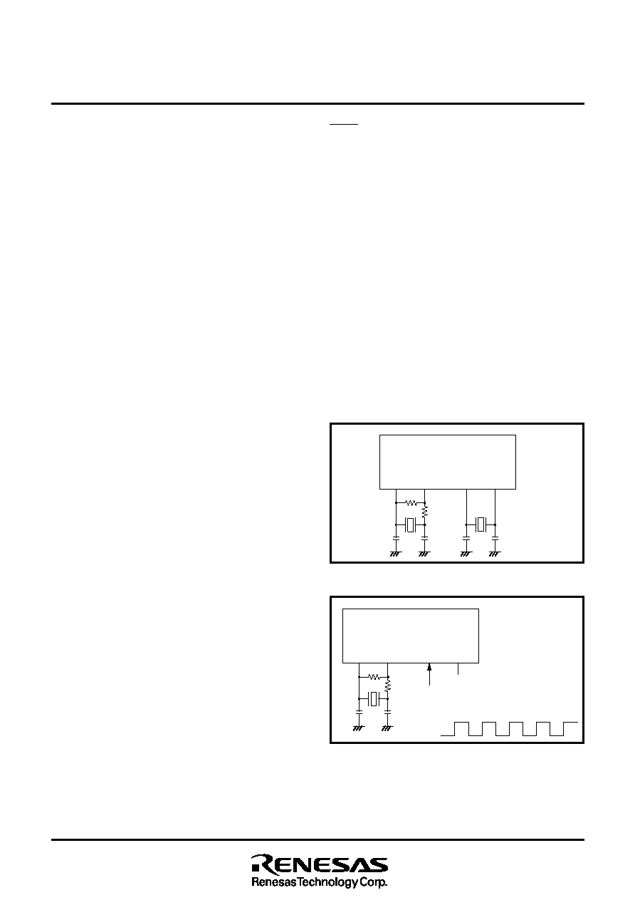
The 7516 group (Spec H) has two built-in oscillation circuits: main
clock XIN-XOUT oscillation circuit and sub clock XCIN-XCOUT oscil-
lation circuit. An oscillation circuit can be formed by connecting a
resonator between XIN and XOUT (XCIN and XCOUT). Use the cir-
cuit constants in accordance with the resonator manufacturer’s
recommended values. No external resistor is needed between XIN
and XOUT since a feed-back resistor exists on-chip. However, an
external feed-back resistor is needed between XCIN and XCOUT.
Immediately after power on, only the XIN oscillation circuit starts
oscillating, and XCIN and XCOUT pins function as I/O ports.
Frequency Control
(1) Middle-speed mode
The internal clock
φ is the frequency of XIN divided by 8. After re-
set is released, this mode is selected.
(2) High-speed mode
The internal clock
φ is half the frequency of XIN.
(3) Low-speed mode
The internal clock
φ is half the frequency of XCIN.
sNote
If you switch the mode between middle/high-speed and low-
speed, stabilize both XIN and XCIN oscillations. The sufficient time
is required for the sub-clock to stabilize, especially immediately af-
ter power on and at returning from the stop mode. When switching
the mode between middle/high-speed and low-speed, set the fre-
quency on condition that f(XIN) > 3f(XCIN).
(4) Low power dissipation mode
The low power consumption operation can be realized by stopping
the main clock XIN in low-speed mode. To stop the main clock, set
bit 5 of the CPU mode register to “1.” When the main clock XIN is
restarted (by setting the main clock stop bit to “0”), set sufficient
time for oscillation to stabilize.
The sub-clock XCIN-XCOUT oscillation circuit can not directly input
clocks that are generated externally. Accordingly, make sure to
cause an external resonator to oscillate.
Oscillation Control
(1) Stop mode
If the STP instruction is executed, the internal clock
φ stops at an
“H” level, and XIN and XCIN oscillation stops. When the oscillation
stabilizing time set after STP instruction released bit is “0,” the
prescaler 12 is set to “FF16” and timer 1 is set to “0116.” When the
oscillation stabilizing time set after STP instruction released bit is
“1,” set the sufficient time for oscillation of used oscillator to stabi-
lize since nothing is set to the prescaler 12 and timer 1.
Either XIN or XCIN divided by 16 is input to the prescaler 12 as
count source. Oscillator restarts when an external interrupt is re-
ceived, but the internal clock
φ is not supplied to the CPU (remains
at “H”) until timer 1 underflows. The internal clock
φ is supplied for
the first time, when timer 1 underflows. This ensures time for the
clock oscillation using the ceramic resonators to be stabilized.
When the oscillator is restarted by reset, apply “L” level to the
Fig. 52 Ceramic resonator circuit
Fig. 53 External clock input circuit
RESET pin until the oscillation is stable since a wait time will not
be generated.
(2) Wait mode
If the WIT instruction is executed, the internal clock
φ stops at an
“H” level, but the oscillator does not stop. The internal clock
φ re-
starts at reset or when an interrupt is received. Since the oscillator
does not stop, normal operation can be started immediately after
the clock is restarted.
To ensure that the interrupts will be received to release the STP or
WIT state, their interrupt enable bits must be set to “1” before ex-
ecuting of the STP or WIT instruction.
When releasing the STP state, the prescaler 12 and timer 1 will
start counting the clock XIN divided by 16. Accordingly, set the
timer 1 interrupt enable bit to “0” before executing the STP instruc-
tion.
sNote
When using the oscillation stabilizing time set after STP instruction
released bit set to “1”, evaluate time to stabilize oscillation of the
used oscillator and set the value to the timer 1 and prescaler 12.
XCIN
XCOUT
XIN
XOUT
CIN
COUT
CCIN
CCOUT
Rf
Rd
XCIN
XCOUT
XIN
XOUT
CCIN
CCOUT
Rf
Rd
Open
External oscillation
circuit
Vcc
Vss
相关PDF资料 |
PDF描述 |
|---|---|
| M37532E8FP | 8-BIT, OTPROM, 6 MHz, MICROCONTROLLER, PDSO36 |
| M37532M4-XXXGP | 8-BIT, MROM, 6 MHz, MICROCONTROLLER, PQFP32 |
| M37534M4-XXXFP | 8-BIT, MROM, 6 MHz, MICROCONTROLLER, PDSO36 |
| M37534M4-XXXGP | 8-BIT, MROM, 6 MHz, MICROCONTROLLER, PQFP32 |
| M37534M4-XXXGP | 8-BIT, MROM, 6 MHz, MICROCONTROLLER, PQFP32 |
相关代理商/技术参数 |
参数描述 |
|---|---|
| M37516M6-XXXHP | 制造商:RENESAS 制造商全称:Renesas Technology Corp 功能描述:SINGLE-CHIP 8-BIT CMOS MICROCOMPUTER |
| M37516M6-XXXKP | 制造商:RENESAS 制造商全称:Renesas Technology Corp 功能描述:SINGLE-CHIP 8-BIT CMOS MICROCOMPUTER |
| M37516M7H-XXXKP | 制造商:RENESAS 制造商全称:Renesas Technology Corp 功能描述:SINGLE-CHIP 8-BIT CMOS MICROCOMPUTER |
| M37516M7-XXXHP | 制造商:RENESAS 制造商全称:Renesas Technology Corp 功能描述:SINGLE-CHIP 8-BIT CMOS MICROCOMPUTER |
| M37516M7-XXXKP | 制造商:RENESAS 制造商全称:Renesas Technology Corp 功能描述:SINGLE-CHIP 8-BIT CMOS MICROCOMPUTER |
发布紧急采购,3分钟左右您将得到回复。