- 您现在的位置:买卖IC网 > PDF目录80563 > M37542F8HP 8-BIT, FLASH, 8 MHz, MICROCONTROLLER, PQCC36 PDF资料下载
参数资料
| 型号: | M37542F8HP |
| 元件分类: | 微控制器/微处理器 |
| 英文描述: | 8-BIT, FLASH, 8 MHz, MICROCONTROLLER, PQCC36 |
| 封装: | 6 X 6 MM, 0.50 MM PITCH, PLASTIC, WQFN-36 |
| 文件页数: | 102/124页 |
| 文件大小: | 1238K |
| 代理商: | M37542F8HP |
第1页第2页第3页第4页第5页第6页第7页第8页第9页第10页第11页第12页第13页第14页第15页第16页第17页第18页第19页第20页第21页第22页第23页第24页第25页第26页第27页第28页第29页第30页第31页第32页第33页第34页第35页第36页第37页第38页第39页第40页第41页第42页第43页第44页第45页第46页第47页第48页第49页第50页第51页第52页第53页第54页第55页第56页第57页第58页第59页第60页第61页第62页第63页第64页第65页第66页第67页第68页第69页第70页第71页第72页第73页第74页第75页第76页第77页第78页第79页第80页第81页第82页第83页第84页第85页第86页第87页第88页第89页第90页第91页第92页第93页第94页第95页第96页第97页第98页第99页第100页第101页当前第102页第103页第104页第105页第106页第107页第108页第109页第110页第111页第112页第113页第114页第115页第116页第117页第118页第119页第120页第121页第122页第123页第124页
7542 Group
Rev.3.03
Jul 11, 2008
Page 77 of 117
REJ03B0006-0303
■ Notes on CPU Rewrite Mode
Take the notes described below when rewriting the flash memory
in CPU rewrite mode.
●Operation speed
During CPU rewrite mode, set the system clock φ to 4.0 MHz or
less using the clock division ratio selection bits (bits 6 and 7 of ad-
dress 003B16).
●Instructions inhibited against use
The instructions which refer to the internal data of the flash
memory cannot be used during CPU rewrite mode.
●Interrupts inhibited against use
The interrupts cannot be used during CPU rewrite mode because
they refer to the internal data of the flash memory.
●Watchdog timer
If the watchdog timer has been already activated, internal reset
due to an underflow will not occur because the watchdog timer is
surely cleared during program or erase.
●Reset
Reset is always valid. The MCU is activated using the boot mode
at release of reset in the condition of CNVss = “H”, so that the pro-
gram will begin at the address which is stored in addresses
FFFC16 and FFFD16 of the boot ROM area.
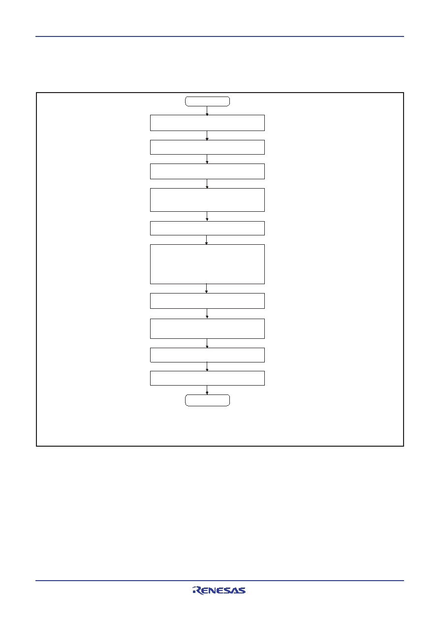
Fig. 101 CPU rewrite mode set/release flowchart
End
Start
Execute read array command or reset flash
memory by setting flash memory reset bit (by
writing “1” and then “0” in succession) (Note 3)
Single-chip mode or Boot mode
Set CPU mode register (Note 1)
Using software command executes erase,
program, or other operation
Jump to control program transferred to internal RAM
(Subsequent operations are executed by control
program in this RAM)
Transfer CPU rewrite mode control program to
internal RAM
Notes1: Set the main clock as follows depending on the clock division ratio selection bits of
Write “0” to CPU rewrite mode select bit
Set CPU rewrite mode select bit to “1”
(by writing “0” and then “1” in succession)
CPU mode register (bits 6, 7 of address 003B16).
2: As for setting of these bits, refer to Table 10.
3: Before exiting the CPU rewrite mode after completing erase or program operation,
Set all user block E/W enable bit
Set 8KB user block E/W mode enable bit
(for setting to “1”, by writing “0” and then “1”
in succession)
(Note 2)
Set all user block E/W enable bit to “0”
Set 8KB user block E/W mode enable bit to “0”
always be sure to execute the read array command or reset the flash memory.
Figure 101 shows a flowchart for setting/releasing CPU rewrite mode.
相关PDF资料 |
PDF描述 |
|---|---|
| M38037M6H-XXXSP | 8-BIT, MROM, 8.4 MHz, MICROCONTROLLER, PDIP64 |
| M38513E4FP | 8-BIT, OTPROM, 4 MHz, MICROCONTROLLER, PDSO42 |
| M37225M8-XXXSP | 8-BIT, MROM, 8.1 MHz, MICROCONTROLLER, PDIP42 |
| M37272EFFP | 8-BIT, OTPROM, 8.1 MHz, MICROCONTROLLER, PDSO42 |
| M37512FCH-XXXHP | 8-BIT, FLASH, 4 MHz, MICROCONTROLLER, PQFP48 |
相关代理商/技术参数 |
参数描述 |
|---|---|
| M37542F8SP | 制造商:RENESAS 制造商全称:Renesas Technology Corp 功能描述:SINGLE-CHIP 8-BIT CMOS MICROCOMPUTER |
| M37542F8SP#U0 | 制造商:Renesas Electronics Corporation 功能描述:MCU 4.0/5.5V 32K PB-FREE 32-SDIP - Trays |
| M37542M2-XXXFP | 制造商:RENESAS 制造商全称:Renesas Technology Corp 功能描述:SINGLE-CHIP 8-BIT CMOS MICROCOMPUTER |
| M37542M2-XXXGP | 制造商:RENESAS 制造商全称:Renesas Technology Corp 功能描述:SINGLE-CHIP 8-BIT CMOS MICROCOMPUTER |
| M37542M2-XXXHP | 制造商:RENESAS 制造商全称:Renesas Technology Corp 功能描述:SINGLE-CHIP 8-BIT CMOS MICROCOMPUTER |
发布紧急采购,3分钟左右您将得到回复。