- 您现在的位置:买卖IC网 > PDF目录67762 > M37630E4FS 8-BIT, UVPROM, 10 MHz, MICROCONTROLLER, CQCC80 PDF资料下载
参数资料
| 型号: | M37630E4FS |
| 元件分类: | 微控制器/微处理器 |
| 英文描述: | 8-BIT, UVPROM, 10 MHz, MICROCONTROLLER, CQCC80 |
| 封装: | 0.80 MM PITCH, CERAMIC, LCC-80 |
| 文件页数: | 15/49页 |
| 文件大小: | 840K |
| 代理商: | M37630E4FS |
第1页第2页第3页第4页第5页第6页第7页第8页第9页第10页第11页第12页第13页第14页当前第15页第16页第17页第18页第19页第20页第21页第22页第23页第24页第25页第26页第27页第28页第29页第30页第31页第32页第33页第34页第35页第36页第37页第38页第39页第40页第41页第42页第43页第44页第45页第46页第47页第48页第49页
MITSUBISHI MICROCOMPUTERS
7630 Group
21
SINGLE-CHIP 8-BIT CMOS MICROCOMPUTER
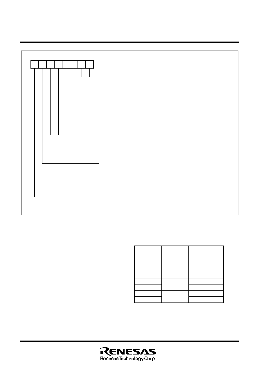
Fig. 19
Structure of timer Y mode register (
φ is internal system clock)
Operating Modes
(1) Timer mode
This mode is available with timer X and timer Y.
Count source
The count source for timer X and Y is the output of the corre-
sponding clock divider. The division ratio can be selected by the
timer Y mode register.
Operation
Both timers X and Y are down counters. On a timer underflow,
the corresponding timer interrupt request bit will be set to “1”, the
contents of the corresponding timer latches will be reloaded to
the counters and counting continues.
(2) Bi-phase counter mode (quadruplicate)
This mode is available with timer X only.
Count source
The count sources are P14/CNTR0 and the P13/TX0 pins.
Operation
Timer X will count both rising and falling edges on both input pins
(see above). Refer to Timer X bi-phase counter mode operation
for the timing chart of the bi-phase counter mode.
The count direction is determined by the edge polarity and level
of count source inputs and may change during the count opera-
tion. Refer to the table below.
On a timer over- or underflow, the corresponding interrupt
request bit will be set to “1” and counting continues.
Timer X count source selection bits
b1 b0
0 0:
φ divided by 4
0 1:
φ divided by 16
1 0:
φ divided by 64
1 1:
φ divided by 128
Timer Y count source selection bits
b3 b2
0 0:
φ divided by 2
0 1:
φ divided by 8
1 0:
φ divided by 32
1 1:
φ divided by 64
Timer Y operation mode bits
b5 b4
0 0: Timer mode
0 1: Pulse period measurement mode
1 0: Event counter mode
1 1: H/L pulse width measurement mode
CNTR1 polarity selection bit
0 : For event counter mode, rising edge active
For interrupt request, falling edge active
For pulse period measurement mode, refer to falling edges
1 : For event counter mode, falling edge active
For interrupt request, rising edge active
For pulse period measurement mode, refer to rising edges
Timer Y stop control bit
0 : Timer counting
1 : Timer stopped
70
Timer Y mode register (address 001F16)
TYM
Table 4: Timer X count direction in Bi-phase counter mode
P13/TX0
P14/CNTR0
Count direction
↑ Edge
LUp
H
Down
↓ Edge
L
Down
HUp
L
↑ Edge
Down
HUp
L
↓ Edge
Up
H
Down
相关PDF资料 |
PDF描述 |
|---|---|
| M37641M8-XXXHP | 8-BIT, MROM, 12 MHz, MICROCONTROLLER, PQFP80 |
| M37641F8HP | 8-BIT, FLASH, 12 MHz, MICROCONTROLLER, PQFP80 |
| M37643F8FP | 8-BIT, FLASH, 12 MHz, MICROCONTROLLER, PQFP80 |
| M37643F8HP | 8-BIT, FLASH, 12 MHz, MICROCONTROLLER, PQFP80 |
| M37643M8-XXXHP | 8-BIT, MROM, 12 MHz, MICROCONTROLLER, PQFP80 |
相关代理商/技术参数 |
参数描述 |
|---|---|
| M37630E4T-XXXFP | 制造商:RENESAS 制造商全称:Renesas Technology Corp 功能描述:SINGLE-CHIP 8-BIT CMOS MICROCOMPUTER |
| M37630E4T-XXXFS | 制造商:MITSUBISHI 制造商全称:Mitsubishi Electric Semiconductor 功能描述:SINGLE-CHIP 8-BIT CMOS MICROCOMPUTER |
| M37630M4T | 制造商:CMLMICRO 制造商全称:CML Microcircuits 功能描述:Baseband Processor for ‘Leisure’ Radios with Data |
| M37630M4T-XXXFP | 制造商:MITSUBISHI 制造商全称:Mitsubishi Electric Semiconductor 功能描述:SINGLE-CHIP 8-BIT CMOS MICROCOMPUTER |
| M37630M4T-XXXFS | 制造商:MITSUBISHI 制造商全称:Mitsubishi Electric Semiconductor 功能描述:SINGLE-CHIP 8-BIT CMOS MICROCOMPUTER |
发布紧急采购,3分钟左右您将得到回复。