- 您现在的位置:买卖IC网 > PDF目录67763 > M37643M8-XXXHP 8-BIT, MROM, 12 MHz, MICROCONTROLLER, PQFP80 PDF资料下载
参数资料
| 型号: | M37643M8-XXXHP |
| 元件分类: | 微控制器/微处理器 |
| 英文描述: | 8-BIT, MROM, 12 MHz, MICROCONTROLLER, PQFP80 |
| 封装: | 12 X 12 MM, 0.50 MM PITCH, PLASTIC, LQFP-80 |
| 文件页数: | 14/120页 |
| 文件大小: | 1253K |
| 代理商: | M37643M8-XXXHP |
第1页第2页第3页第4页第5页第6页第7页第8页第9页第10页第11页第12页第13页当前第14页第15页第16页第17页第18页第19页第20页第21页第22页第23页第24页第25页第26页第27页第28页第29页第30页第31页第32页第33页第34页第35页第36页第37页第38页第39页第40页第41页第42页第43页第44页第45页第46页第47页第48页第49页第50页第51页第52页第53页第54页第55页第56页第57页第58页第59页第60页第61页第62页第63页第64页第65页第66页第67页第68页第69页第70页第71页第72页第73页第74页第75页第76页第77页第78页第79页第80页第81页第82页第83页第84页第85页第86页第87页第88页第89页第90页第91页第92页第93页第94页第95页第96页第97页第98页第99页第100页第101页第102页第103页第104页第105页第106页第107页第108页第109页第110页第111页第112页第113页第114页第115页第116页第117页第118页第119页第120页
110
7643 Group
SINGLE-CHIP 8-BIT CMOS MICROCOMPUTER
MITSUBISHI MICROCOMPUTERS
PRELIMINAR
Y
Notice:
This
is not
a final
specification.
Some
parametric
limits
are
subject
to
change.
qStatus Register 1 (SRD1)
The status register 1 indicates the status of serial communica-
tions, results from ID checks and results from check sum
comparisons. It can be read after the status register (SRD) by writ-
ing the read status register command (7016). Also, status register
1 is cleared by writing the clear status register command (5016).
Table 26 lists the definition of each status register 1 bit. This regis-
ter becomes “0016” when power is turned on and the flag status is
maintained even after the reset.
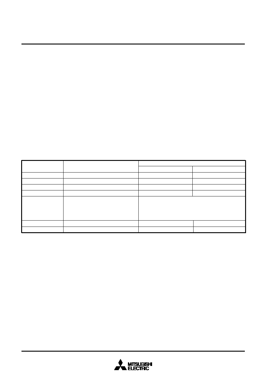
Table 26 Definition of each bit of status register 1 (SRD1)
00
Not verified
01
Verification mismatch
10
Reserved
11
Verified
SR15 (bit7)
SR14 (bit6)
SR13 (bit5)
SR12 (bit4)
SR11 (bit3)
SR10 (bit2)
SR9 (bit1)
SR8 (bit0)
Boot update completed bit
Reserved
Checksum match bit
ID code check completed bits
Data reception time out
Reserved
“1”
Update completed
-
Match
Time out
-
“0”
Not Update
-
Mismatch
Normal operation
-
Definition
SRD1 bits
Status name
Boot update completed bit (SR15)
This flag indicates whether the control program was downloaded
to the RAM or not, using the download function.
Check sum consistency bit (SR12)
This flag indicates whether the check sum matches or not when a
program, is downloaded for execution using the download func-
tion.
ID code check completed bits (SR11 and SR10)
These flags indicate the result of ID code checks. Some com-
mands cannot be accepted without an ID code check.
Data reception time out (SR9)
This flag indicates when a time out error is generated during data
reception. If this flag is attached during data reception, the re-
ceived data is discarded and the MCU returns to the command
wait state.
相关PDF资料 |
PDF描述 |
|---|---|
| M37702S1LGP | 16-BIT, 8 MHz, MICROCONTROLLER, PQFP80 |
| M37702M2LXXXGP | 16-BIT, MROM, 8 MHz, MICROCONTROLLER, PQFP80 |
| M37702M2LXXXHP | 16-BIT, MROM, 8 MHz, MICROCONTROLLER, PQFP80 |
| M37703MDBSP | 16-BIT, MROM, 25 MHz, MICROCONTROLLER, PDIP64 |
| M37721S1BFP | 16-BIT, 25 MHz, MICROCONTROLLER, PQFP100 |
相关代理商/技术参数 |
参数描述 |
|---|---|
| M3764A-12 | 制造商:OK International 功能描述: |
| M3765 | 制造商:未知厂家 制造商全称:未知厂家 功能描述:HORN/SIREN WITH SOFT CHIRP 6 ALARM SOUNDS |
| M3766 | 制造商:未知厂家 制造商全称:未知厂家 功能描述:HORN/SIREN WITH SOFT CHIRP 6 ALARM SOUNDS |
| M37702E2LGP | 制造商:Mitsubishi Electric 功能描述: |
| M37702E4BFS | 制造商:Renesas Electronics Corporation 功能描述:EPROM MCU/8BIT CMOS EMULATION CHIP - Bulk |
发布紧急采购,3分钟左右您将得到回复。