- 您现在的位置:买卖IC网 > PDF目录80580 > M38514E6SP 8-BIT, OTPROM, 4 MHz, MICROCONTROLLER, PDIP42 PDF资料下载
参数资料
| 型号: | M38514E6SP |
| 元件分类: | 微控制器/微处理器 |
| 英文描述: | 8-BIT, OTPROM, 4 MHz, MICROCONTROLLER, PDIP42 |
| 封装: | 0.600 INCH, 1.78 MM PITCH, PLASTIC, SDIP-42 |
| 文件页数: | 13/91页 |
| 文件大小: | 1161K |
| 代理商: | M38514E6SP |
第1页第2页第3页第4页第5页第6页第7页第8页第9页第10页第11页第12页当前第13页第14页第15页第16页第17页第18页第19页第20页第21页第22页第23页第24页第25页第26页第27页第28页第29页第30页第31页第32页第33页第34页第35页第36页第37页第38页第39页第40页第41页第42页第43页第44页第45页第46页第47页第48页第49页第50页第51页第52页第53页第54页第55页第56页第57页第58页第59页第60页第61页第62页第63页第64页第65页第66页第67页第68页第69页第70页第71页第72页第73页第74页第75页第76页第77页第78页第79页第80页第81页第82页第83页第84页第85页第86页第87页第88页第89页第90页第91页
Rev.1.01
Oct 15, 2003
page 20 of 89
3851 Group (Built-in 24 KB or more ROM)
TIMERS
The 3851 group (built-in 24 KB or more ROM) has four timers:
timer X, timer Y, timer 1, and timer 2.
The division ratio of each timer or prescaler is given by 1/(n + 1),
where n is the value in the corresponding timer or prescaler latch.
All timers are count down. When the timer reaches “0016”, an un-
derflow occurs at the next count pulse and the corresponding
timer latch is reloaded into the timer and the count is continued.
When a timer underflows, the interrupt request bit corresponding
to that timer is set to “1”.
Timer X and Timer Y
Timer X and Timer Y can each select in one of four operating
modes by setting the timer XY mode register.
(1) Timer Mode
The timer counts the count source selected by Timer count source
selection bit.
(2) Pulse Output Mode
The timer counts the count source selected by Timer count source
selection bit. Whenever the contents of the timer reach “0016”, the
signal output from the CNTR0 (or CNTR1) pin is inverted. If the
CNTR0 (or CNTR1) active edge selection bit is “0”, output begins
at “ H”.
If it is “1”, output starts at “L”. When using a timer in this mode, set
the corresponding port P27 ( or port P40) direction register to out-
put mode.
(3) Event Counter Mode
Operation in event counter mode is the same as in timer mode,
except that the timer counts signals input through the CNTR0 or
CNTR1 pin.
When the CNTR0 (or CNTR1) active edge selection bit is “0”, the
rising edge of the CNTR0 (or CNTR1) pin is counted.
When the CNTR0 (or CNTR1) active edge selection bit is “1”, the
falling edge of the CNTR0 (or CNTR1) pin is counted.
(4) Pulse Width Measurement Mode
If the CNTR0 (or CNTR1) active edge selection bit is “0”, the timer
counts the selected signals by the count source selection bit while
the CNTR0 (or CNTR1) pin is at “H”. If the CNTR0 (or CNTR1) ac-
tive edge selection bit is “1”, the timer counts it while the CNTR0
(or CNTR1) pin is at “L”.
The count can be stopped by setting “1” to the timer X (or timer Y)
count stop bit in any mode. The corresponding interrupt request
bit is set each time a timer underflows.
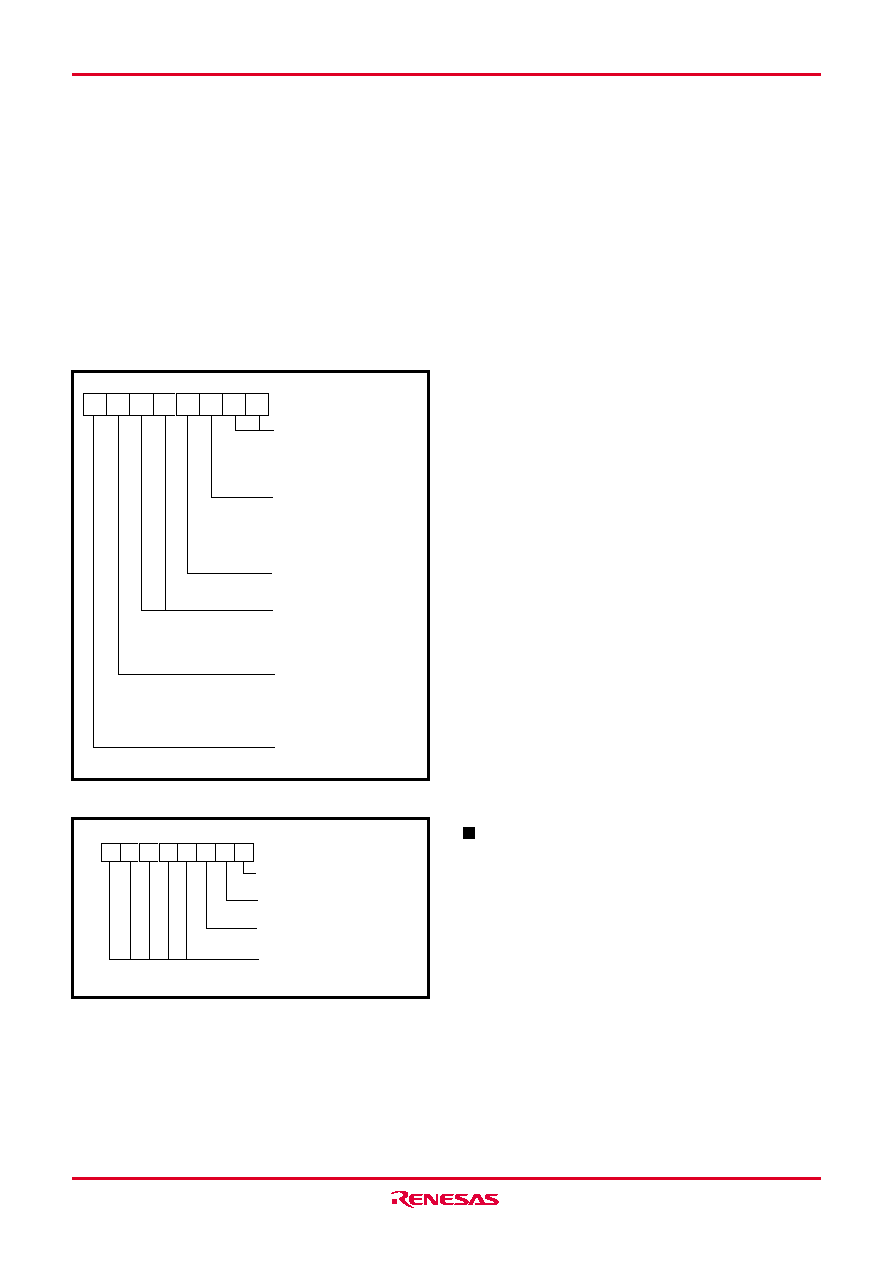
Fig. 15 Structure of timer XY mode register
Note
When switching the count source by the timer 12, X and Y count
source bits, the value of timer count is altered in unconsiderable
amount owing to generating of a thin pulses in the count input
signals.
Therefore, select the timer count source before set the value to
the prescaler and the timer.
When timer X/timer Y underflow while executing the instruction
which sets “1” to the timer X/timer Y count stop bits, the timer X/
timer Y interrupt request bits are set to “1”. Timer X/Timer Y in-
terrupts are received if these interrupts are enabled at this time.
The timing which interrupt is accepted has a case after the in-
struction which sets “1” to the count stop bit, and a case after
the next instruction according to the timing of the timer under-
flow. When this interrupt is unnecessary, set “0” (disabled) to the
interrupt enable bit and then set “1” to the count stop bit.
Fig. 16 Structure of timer count source selection register
Timer 1 and Timer 2
The count source of prescaler 12 is the oscillation frequency
which is selected by timer 12 count source selection bit. The out-
put of prescaler 12 is counted by timer 1 and timer 2, and a timer
underflow sets the interrupt request bit.
Timer X count stop bit
0: Count start
1: Count stop
Timer XY mode register
(TM : address 002316)
Timer Y operating mode bits
0 0: Timer mode
0 1: Pulse output mode
1 0: Event counter mode
1 1: Pulse width measurement mode
CNTR1 active edge selection bit
0: Interrupt at falling edge
Count at rising edge in event
counter mode
1: Interrupt at rising edge
Count at falling edge in event
counter mode
b7
CNTR0 active edge selection bit
0: Interrupt at falling edge
Count at rising edge in event
counter mode
1: Interrupt at rising edge
Count at falling edge in event
counter mode
b0
Timer X operating mode bits
0 0: Timer mode
0 1: Pulse output mode
1 0: Event counter mode
1 1: Pulse width measurement mode
b1b0
b5b4
Timer Y count stop bit
0: Count start
1: Count stop
Timer count source selection register
(TCSS : address 002816)
b7
b0
Timer X count source selection bit
0 : f(XIN)/16 (f(XCIN)/16 at low-speed mode)
1 : f(XIN)/2 (f(XCIN)/2 at low-speed mode)
Timer Y count source selection bit
0 : f(XIN)/16 (f(XCIN)/16 at low-speed mode)
1 : f(XIN)/2 (f(XCIN)/2 at low-speed mode)
Timer 12 count source selection bit
0 : f(XIN)/16 (f(XCIN)/16 at low-speed mode)
1 : f(XCIN)
Not used (returns “0” when read)
相关PDF资料 |
PDF描述 |
|---|---|
| M37477M8-XXXFP | 8-BIT, MROM, 8 MHz, MICROCONTROLLER, PDSO32 |
| M38073M4-XXXFP | 8-BIT, MROM, 4 MHz, MICROCONTROLLER, PQFP80 |
| M38K27M4L-XXXHP | 8-BIT, MROM, 8 MHz, MICROCONTROLLER, PQFP64 |
| M30302MC-XXXFP | 16-BIT, MROM, 16 MHz, MICROCONTROLLER, PQFP100 |
| M37480E8-XXXSP | 8-BIT, OTPROM, 4 MHz, MICROCONTROLLER, PDIP32 |
相关代理商/技术参数 |
参数描述 |
|---|---|
| M38517T-ADS | 功能描述:DEV TMP TRGT BRD FOR M38517RSS & RoHS:否 类别:编程器,开发系统 >> 配件 系列:- 标准包装:1 系列:- 附件类型:适配器板 适用于相关产品:RCB230,RCB231,RCB212 配用:26790D-ND - RCB BREAKOUT BOARD RS232 CABLE |
| M38517T-PAC | 功能描述:DEV SIMPLE TOOL EMULATOR FOR M38 RoHS:否 类别:编程器,开发系统 >> 内电路编程器、仿真器以及调试器 系列:- 产品变化通告:Development Systems Discontinuation 19/Jul/2010 标准包装:1 系列:* 类型:* 适用于相关产品:* 所含物品:* |
| M3852 BK001 | 制造商:Alpha Wire 功能描述:CBL 8COND 14AWG BLK 1000' |
| M3852 BK002 | 制造商:Alpha Wire 功能描述:CBL 8COND 14AWG BLK 500' |
| M3852 BK005 | 制造商:Alpha Wire 功能描述:CBL 8COND 14AWG BLK 100' |
发布紧急采购,3分钟左右您将得到回复。