- 您现在的位置:买卖IC网 > PDF目录80411 > M38C13E6HP 8-BIT, OTPROM, 8 MHz, MICROCONTROLLER, PQFP64 PDF资料下载
参数资料
| 型号: | M38C13E6HP |
| 元件分类: | 微控制器/微处理器 |
| 英文描述: | 8-BIT, OTPROM, 8 MHz, MICROCONTROLLER, PQFP64 |
| 封装: | 10 X 10 MM, PLASTIC, LQFP-64 |
| 文件页数: | 33/59页 |
| 文件大小: | 955K |
| 代理商: | M38C13E6HP |
第1页第2页第3页第4页第5页第6页第7页第8页第9页第10页第11页第12页第13页第14页第15页第16页第17页第18页第19页第20页第21页第22页第23页第24页第25页第26页第27页第28页第29页第30页第31页第32页当前第33页第34页第35页第36页第37页第38页第39页第40页第41页第42页第43页第44页第45页第46页第47页第48页第49页第50页第51页第52页第53页第54页第55页第56页第57页第58页第59页
SINGLE-CHIP 8-BIT CMOS MICROCOMPUTER
MITSUBISHI MICROCOMPUTERS
38C1 Group
39
CLOCK GENERATING CIRCUIT
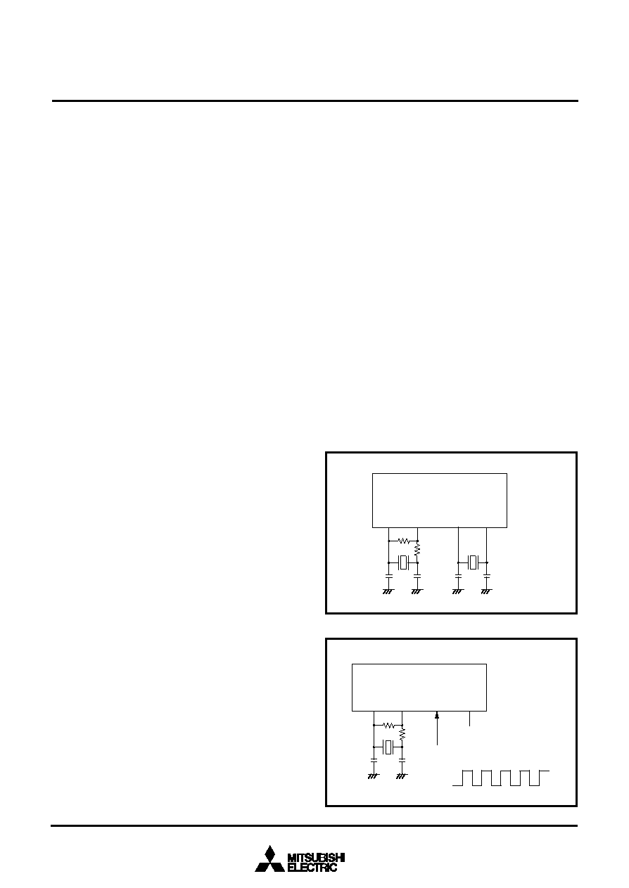
The oscillation circuit of 38C1 group can be formed by connecting
an oscillator, capacitor and resistor between XIN and XOUT (XCIN
and XCOUT). To supply a clock signal externally, input it to the XIN
pin and make the XOUT pin open. The clocks that are externally
generated cannot be directly input to XCIN. Use the circuit con-
stants in accordance with the oscillator manufacturer's recom-
mended values. No external resistor is needed between XIN and
XOUT since a feed-back resistor exists on-chip. However, a 10 M
external feed-back resistor is needed between XCIN and XCOUT.
Immediately after reset is released, only the built-in ring oscillator
starts oscillating, XIN -XOUT oscillation stops oscillating, and XCIN
and XCOUT pins function as I/O ports.
Operation mode
(1) Ring oscillator mode
The internal clock
φ is the built-in ring oscillator oscillation divided
by 8.
(2) Middle-speed mode
The internal clock
φ is the frequency of XIN divided by 8.
(3)High-speed mode
The internal clock
φ is half the frequency of XIN.
(4) Low-speed mode
The internal clock
φ is half the frequency of XCIN.
After reset release and when system returns from the stop mode,
the ring oscillator mode is selected.
Refer to the clock state transition diagram for the setting of transi-
tion to each mode.
The XIN–XOUT oscillation is controlled by the bit 5 of CPUM, and
the sub-clock oscillation is controlled by the bit 4 of CPUM. When
the mode is switched to the ring oscillator mode, set the bit 3 of
CPUM to “1”.
In the ring oscillator mode, the oscillation by the oscillator can be
stopped. In the low-speed mode, the power consumption can be
reduced by stopping the XIN–XOUT oscillation.
When the mode is switched from the ring oscillator mode to the
low-speed mode, the built-in ring oscillator is stopped.
Set enough time for oscillation to stabilize by programming to re-
start the stopped oscillation and switch the operation mode. Also,
set enough time for oscillation to stabilize by programming to
switch the timer count source .
Note: If you switch the mode between ring oscillator mode,
middle/high-speed mode and low-speed mode, stabilize
both XIN and XCIN oscillations. Especially be careful imme-
diately after power-on and at returning from stop mode. Re-
fer to the clock state transition diagram for the setting of
transition to each mode. Set the frequency in the condition
that f(XIN) > 3f(XCIN).
When the middle- and high-speed mode are not used (XIN-
XOUT oscillation and external clock input are not
performed), connect XIN to VCC through a resistor.
Fig. 40 Oscillator circuit
Fig. 41 External clock input circuit
Oscillation Control
(1) Stop mode
Set the timer 1 interrupt enable bit to disabled (“0”) before execut-
ing the STP instruction. If the STP instruction is executed, the in-
ternal clock
φ stops at an “H” level, and main clock, ring oscillator
and sub-clock oscillators stop.
In this time, “0116” is set to timer 1 and the ring oscillator is con-
nected forcibly for the system clock and the timer 1 count source.
Also, the bits of the timer 123 mode register except bit 4 are
cleared to “0”.
When an external interrupt is received, the clock oscillated before
stop mode and the ring oscillator start oscillating.
However, bit 3 of CPUM is set to “1” forcibly and system returns to
the ring oscillator mode.
Tthe internal clock
φ is supplied to the CPU after timer 1
underflows. However, when the system clock is switched from the
ring oscillator to main clock and sub-clock, generate the wait time
enough for oscillation stabilizing by program.
(2) Wait mode
If the WIT instruction is executed, only the internal clock
φ stops at
an “H” level. The states of main clock, ring oscillator and sub-clock
are the same as the state before the executing the WIT instruction
and the oscillation does not stop. Since the internal clock
φ re-
starts when an interrupt is received, the instruction is executed im-
mediately.
XCIN
CIN
COUT
CCIN
CCOUT
Rf
Rd
XOUT
XIN
XCOUT
External oscillation circuit
Open
VCC
VSS
CCIN
Rf
Rd
CCOUT
XCIN
XOUT
XIN
XCOUT
相关PDF资料 |
PDF描述 |
|---|---|
| MSM80C31F-XXXRS | 8-BIT, MROM, 12 MHz, MICROCONTROLLER, PDIP40 |
| MB91F133APBT | 32-BIT, FLASH, 33 MHz, RISC MICROCONTROLLER, PBGA144 |
| MPC8255ACZUIFBX | 32-BIT, 200 MHz, RISC PROCESSOR, PBGA480 |
| MPC8264ACZUIHBX | 32-BIT, 200 MHz, RISC PROCESSOR, PBGA480 |
| MPC8265ACZUIFBX | 32-BIT, 200 MHz, RISC PROCESSOR, PBGA480 |
相关代理商/技术参数 |
参数描述 |
|---|---|
| M38C13RLFS | 制造商:Renesas Electronics Corporation 功能描述:EMULATION MCU/8BIT CMOS EMULATION CHIP - Bulk |
| M38C24M4-XXXFP | 制造商:MITSUBISHI 制造商全称:Mitsubishi Electric Semiconductor 功能描述:SINGLE-CHIP 8-BIT CMOS MICROCOMPUTER |
| M38C24M4-XXXHP | 制造商:MITSUBISHI 制造商全称:Mitsubishi Electric Semiconductor 功能描述:SINGLE-CHIP 8-BIT CMOS MICROCOMPUTER |
| M38C24M6-051HP | 制造商:MITSUBISHI 制造商全称:Mitsubishi Electric Semiconductor 功能描述:SINGLE-CHIP 8-BIT CMOS MICROCOMPUTER |
| M38C24M6-XXXFP | 制造商:MITSUBISHI 制造商全称:Mitsubishi Electric Semiconductor 功能描述:SINGLE-CHIP 8-BIT CMOS MICROCOMPUTER |
发布紧急采购,3分钟左右您将得到回复。