- 您现在的位置:买卖IC网 > PDF目录263461 > M4002-150M (VALPEY FISHER CORP) CRYSTAL OSCILLATOR, CLOCK, 150 MHz, HCMOS/LSTTL OUTPUT PDF资料下载
参数资料
| 型号: | M4002-150M |
| 厂商: | VALPEY FISHER CORP |
| 元件分类: | XO, clock |
| 英文描述: | CRYSTAL OSCILLATOR, CLOCK, 150 MHz, HCMOS/LSTTL OUTPUT |
| 封装: | HERMETIC SEALED PACKAGE-14/4 |
| 文件页数: | 2/2页 |
| 文件大小: | 4607K |
| 代理商: | M4002-150M |
FULL SIZE D.I.L
M package
M1254, M1256,
M1258
M3254, M3256,
M3258
M4001 thru M4009
M4301 thru M4309
HALF SIZE D.I.L
H package
H1254, H1256,
H1258
H3254, H3256,
H3258
H4001 thru H4009
H4301 thru H4309
ENVIRONMENTAL SPECIFICATIONS
Shock – 1000 Gs, 0.35 ms, 1/2 sine wave, 3 shocks in each plane
Vibration – 10-2000 Hz of .06" d.a. or 20 Gs, whichever is less
Humidity – Resistant to 85° R.H. at 85°C
MECHANICAL SPECIFICATIONS
Leak – MIL STD 883, Method 1014, condition A1
Pins – Alloy 52, nickel plated with 60/40 solder coat, or 7 microinch gold
over nickel
Bend Test – Will withstand two bends of 90° from reference
Header – Steel, with nickel plate, or 7 microinch gold over nickel
Case – Stainless steel, type 304
Marking – Epoxy ink or laser engraved
Resistance to Solvents – MIL STD 202, Method 215
CRYSTAL OSCILLATORS
HCMOS 5V
Thru-Hole
Extended Temperature/COTS
20 KHz to 150 MHz
ELECTRICAL SPECIFICATIONS
Frequency Range
20 KHz to 150 MHz
Frequency Stability Includes calibration at 25°C, operating temperature,
change of input voltage, change of load, shock and
vibration.
Output
All units, full range
Loads
3 TLL loads, or 10 LSTTL loads, or 15 pf CMOS
TYP
MAX
UNITS
Input Voltage
5.0 ± 0.5
volts
Input Current
40
mA
Jitter
From positive edge to positive edge
50
ps RMS
Rise and Fall Time
TTL and LSTTL from 0.4 to 2.4V
10
ns
CMOS, 15pf, from 0.4 to (VDD -0.4) V
10
ns
CMOS, 30pf, from 0.4 to (VDD -0.4) V
20
ns
Symmetry *
TTL and LSTTL @ 1.4V
40/60
percent
CMOS @50% VDD
40/60
percent
Aging
First year
3
ppm
After first year
1
ppm/yr
* Superior symmetry available on all models.
CONNECTIONS
HOW TO ORDER
For Part Number, put package type before model number,
and add frequency in MHz, for example:
“M” is full size DIL
“H” is half size DIL
“4309”
is model
type
H
4309 - 16M
“16 M”
frequency
in MHz
PIN
1
NOT USED
Floating or “1”: Oscillator runs
Ground or “0”: Disable or Tristate
FULL HALF
Fixed
SIZE
Output
Tristate
PIN
7
4
Ground and Case
PIN
8
5
Output
PIN
14
8
5V, VDD
1
(1)
(8)
(4)
(5)
14
7
8
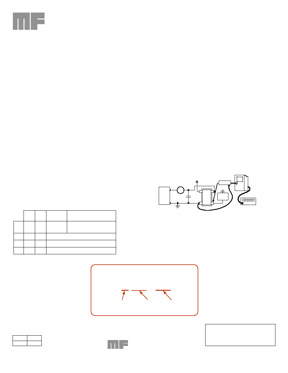
LOAD
MA
GND
IMF
5V
Power
Supply
FET PROBE
350 MHz
SCOPE
Y-OUTPUT
COUNTER
V
DD
ENABLE – DISABLE
“ONE” OR “ZERO”
To adapt Fet probe to receptacle
use Tektronix Part #103-0164-00
To connect output to scope use
use Tektronix Part #131-0258-00 (receptacle)
Half can connectors shown in ( ).
ALL OSCILLATORS HAVE INTERNAL BYPASS CAPACITORS
TEST CIRCUIT
V
DD
2 of 2
SS#
Rev.
M1254
A
Unless customer-specific terms and conditions
are signed by an officer of MF Electronics, the
sale of this and all MF Electronics products are
subject to terms and conditions set forth at
www.mfelectronics.com/terms
USA Sales: +1.800.982.5737 508-435-6831 Fax: 508-497-6377 www.valpeyfisher.com email:salesvalpeyfisher.com
ELECTRONICS
10 Commerce Dr
New Rochelle NY 10801
相关PDF资料 |
PDF描述 |
|---|---|
| M4308-16M | CRYSTAL OSCILLATOR, CLOCK, 16 MHz, HCMOS/LSTTL OUTPUT |
| MHO367TAD80.0000MHZ | CRYSTAL OSCILLATOR, CLOCK, 80 MHz, HCMOS/TTL OUTPUT |
| MHO372TADFREQ | CRYSTAL OSCILLATOR, CLOCK, 1.5 MHz - 80 MHz, HCMOS/TTL OUTPUT |
| M5RJ14ZQJFREQ | CRYSTAL OSCILLATOR, CLOCK, 19.44 MHz - 170 MHz, PECL OUTPUT |
| MHO+73TBG-R-FREQ1-OUT3 | CRYSTAL OSCILLATOR, CLOCK, 1 MHz - 2.99 MHz, TTL OUTPUT |
相关代理商/技术参数 |
参数描述 |
|---|---|
| M4002-160600 | 制造商:Nortools International Ltd 功能描述:SDS DRILL 16X600 |
| M4002-200310 | 制造商:Nortools International Ltd 功能描述:SDS DRILL 20X310 |
| M4002-200450 | 制造商:Nortools International Ltd 功能描述:SDS DRILL 20X450 |
| M400273VSJ | 制造商:MTRONPTI 制造商全称:MTRONPTI 功能描述:9x14 mm, 5.0 or 3.3 Volt, Sinewave, VCSO |
| M400273VSJ-R | 制造商:MTRONPTI 制造商全称:MTRONPTI 功能描述:9x14 mm, 5.0 or 3.3 Volt, Sinewave, VCSO |
发布紧急采购,3分钟左右您将得到回复。