参数资料
| 型号: | MA240013 |
| 厂商: | Microchip Technology |
| 文件页数: | 1/4页 |
| 文件大小: | 0K |
| 描述: | MODULE PLUG-IN PIC24 44-PIN |
| 标准包装: | 1 |
| 系列: | PIC® |
| 附件类型: | 插拔式模块(PIM)- PIC24FJ64GA004 |
| 适用于相关产品: | Explorer 16(DM240001 或 DM240002) |
| 产品目录页面: | 658 (CN2011-ZH PDF) |
�� �
�
�Introducing� the� PIC24FJ64GA004� PIM�
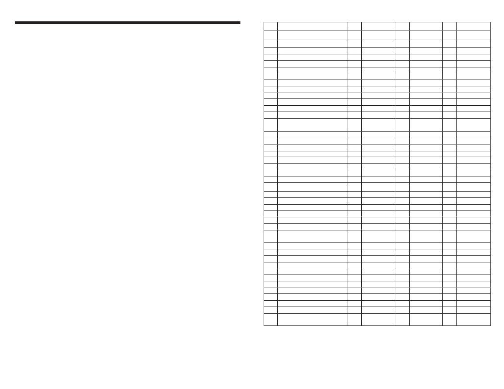
�Table� 1:� 44-Pin� to� 100-Pin� Pinout�
�Overview�
�The� PIC24FJ64GA004� PIM� is� designed� to� demonstrate� the� capabilities� of� the� PIC24FJ64GA004�
�family� using� the� Explorer� 16� Demonstration� Board� kit� and� the� PICtail?� Plus� daughter� boards.� The�
�PIC24FJ64GA004� is� a� 44-pin� device� with� the� new� Peripheral� Pin� Select� (PPS)� feature.� The� PPS�
�feature� of� this� PIC24F� family� allows� many� of� the� digital� peripherals� on� the� part� to� be� remapped�
�to� use� any� of� a� number� of� pins� on� the� device.� This� allows� for� signi� ?� cant� improvements� in� ease� of�
�design� and� helps� to� reduce� cost� by� allowing� for� the� smallest� possible� size� devices� to� be� used.�
�Pin� #�
�1�
�2�
�3�
�4�
�5�
�PIC24FJ64GA004� Pinout�
�RP9/SDA1/CN21/PMPD3/RB9�
�RP22/CN18/PMPA1/RC6�
�RP23/CN17/PMPA0/RC7�
�RP24/CN20/PMPA5/RC8�
�RP25/CN19/PMPA6/RC9�
�Pin� #�
�59�
�92�
�44�
�67�
�50�
�PIM� Func� #1�
�RA3/SDA2�
�RA7�
�PMA0�
�RA15/INT4� (1)�
�U2TX�
�Pin� #�
�99�
�23�
�48�
�66�
�PIM� Func� #2�
�PMD3�
�RB2/SS1� (1)�
�RD15/U1RTS� (1)�
�RA14/INT3� (1)�
�Pin� #�
�43�
�10�
�29�
�PIM� Func� #3�
�PMA1�
�PMA5/SCK2�
�PMA6�
�The� following� two� tables� detail� the� pin� mapping� of� the� 44-pin� device� to� the� 100-pin� PIM� header.�
�?� The� 44-pin� to� 100-pin� table� lists� the� device� pins� and� shows� what� functions� are� mapped� to� each.�
�6�
�7�
�8�
�DISVREG�
�V� CAP� /V� DDCORE�
�RP10/CN16/PMPD2/RB10�
�75�
�85�
�98�
�GND�
�V� CAP� /V� DDCORE�
�PMD2�
�This� table� is� most� useful� for� viewing� multiplexing� con� ?� icts� which� prevent� some� functions� from�
�being� used� simultaneously.�
�?� The� 100-pin� to� 44-pin� table� shows� a� listing� of� the� Explorer� 16� functions� and� what� device� pin� is�
�mapped� to� that� function.�
�9�
�10�
�11�
�12�
�RP11/CN15/PMPD1/RB11�
�RP12/CN14/PMPD0/RB12�
�RP13/CN13/PMPRD/RB13�
�PMPA10/RA10/TMS�
�94�
�91�
�82�
�17�
�PMD1�
�RA6�
�PMRD�
�RA0/TMS�
�93�
�83�
�PMD0�
�RD6�
�PIC24FJ64GA004� PIM� Features�
�Due� to� the� ?� exibility� allowed� by� the� PPS� feature,� the� 44-pin� device� is� capable� of� performing� all� of� the�
�base� functions� on� the� 100-pin� Explorer� 16� board.� In� addition,� the� PIM� is� compatible� with� most� of� the�
�PICtail� Plus� daughter� boards� for� the� Explorer� 16.�
�PIC24FJ64GA004� PIM� Limitations�
�The� result� of� multiplexing� the� functions� from� a� 44-pin� part� to� the� 100-pin� PIM� header� is� that� many� of�
�the� functions� cannot� be� used� simultaneously.� All� of� the� built-in� functionality� on� the� Explorer� 16� board�
�can� be� used� simultaneously,� with� the� exception� of� the� LEDs.� LEDs� are� multiplexed� on� switch� and�
�13�
�14�
�15�
�16�
�17�
�18�
�19�
�20�
�PMPA7/RA7/TCK�
�AN10/CV� REF� /RTCC/RP14/CN12/�
�PMPWR/RB14�
�AN9/RP15/C11/PMPCS1/RB15�
�AV� SS�
�AV� DD�
�NMCLR�
�AN0/CV� REF� +/CN2/RA0�
�AN1/CV� REF� -/CN3/RA1�
�38�
�68�
�55�
�31�
�30�
�13�
�25�
�24�
�RA1/TCK�
�RTCC/RD8� (1)�
�SCK1�
�AV� SS�
�AV� DD�
�NMCLR�
�RB0/AN0� (1)�
�RB1/AN1� (1)�
�80�
�81�
�7�
�72�
�32�
�RD13�
�PMWR�
�RC2/T3CK� (1)�
�RD0� (1)�
�RB8/AN8� (1)�
�28�
�71�
�33�
�9�
�PMA7�
�PMCS1�
�RB9/AN9� (1)�
�RC4� (1)�
�PMP� lines,� which� means� they� will� not� always� be� usable� if� these� functions� are� in� use.�
�21�
�AN2/C2IN-/RP0/CN4/RB0/PGD1�
�27�
�PGD�
�The� PICtail� Plus� daughter� boards� have� similar� limitations.� All� daughter� boards� will� work� by�
�themselves,� however,� most� PICtail� Plus� daughter� boards� will� not� work� if� two� are� installed�
�simultaneously.� Additionally,� a� PICtail� Plus� daughter� board� may� not� work� with� all� of� the� default�
�Explorer� 16� functionality.� If� a� PICtail� Plus� daughter� board� is� designed� to� work� with� a� Microchip� stack,�
�the� stack� will� need� to� be� modi� ?� ed� to� function� with� the� PIM� pinout� and� PPS� feature.�
�Please� check� the� pinouts� of� the� components� you� are� using� to� ensure� compatability� before� attempting�
�22�
�23�
�24�
�25�
�26�
�27�
�AN3/C2IN+/RP1/CN5/RB1/PGC1�
�AN4/C1IN-/RP2/SDA2/CN6/RB2�
�AN5/C1IN+/RP3/SCL2/CN7/RB3�
�AN6/RP16/CN8/RC0�
�AN7/RP17/CN9/RC1�
�AN8/RP18/CN10/PMPA2/RC2�
�26�
�56�
�57�
�21�
�20�
�22�
�PGC�
�SDA1/RG2� (1)�
�SCL1/RG3� (1)�
�RB4/AN4�
�RB5/AN5�
�RB3/AN3� (1)�
�87�
�88�
�53�
�54�
�18�
�RF0� (1)�
�RF1� (1)�
�SDO1�
�SDI1�
�RE8/INT1� (1)�
�19�
�47�
�51�
�52�
�14�
�RE9/INT2� (1)�
�RD14/U1CTS� (1)�
�U1TX�
�U1RX�
�PMA2/SS2�
�to� use� multiple� peripheral� functions� or� PICtail� Plus� daughter� boards� at� the� same� time.�
�Tips� for� Using� the� PIC24FJ64GA004� PIM�
�?� The� Explorer� 16� LEDs� are� multiplexed� with� a� number� of� functions� and� so� may� not� be� useful� in�
�28�
�29�
�30�
�31�
�V� DD�
�V� SS�
�OSCI/CLKI/CN30/RA2�
�OSCO/CLKO/CN29/RA3�
�16�
�15�
�63�
�64�
�V� DD�
�V� SS�
�OSC1�
�OSC2�
�some� situations.� Make� sure� to� check� the� mapping� tables� for� con� ?� icts.�
�?� The� PIC24FJ64GA004� port� pins� are� not� mapped� to� the� corresponding� port� I/O� on� the� Explorer� 16.�
�Make� sure� to� use� the� following� pinout� tables� as� a� cross� reference� to� ensure� you� use� the� correct�
�device� pin� in� your� application.�
�32�
�33�
�34�
�35�
�PMPA8/RA8/TDO�
�SOSCI/RP4/CN1/RB4�
�SOSCO/T1CK/CN0/RA4�
�PMPA9/RA9/TDI�
�61�
�73�
�74�
�60�
�RA5/TDO�
�SOSCI�
�SOSCO�
�RA4/TDI�
�79�
�84�
�RD12�
�RD7�
�?� Many� of� the� peripherals� used� by� the� Explorer� 16� and� PICtail� Plus� daughter� boards� are�
�implemented� on� pins� with� analog� functionality.� These� peripherals� may� not� con� ?� ict� with� analog�
�features� on� other� PIC24F� PIMs.� Make� sure� to� add� any� necessary� code� to� override� this� analog�
�36�
�37�
�38�
�RP19/CN28/PMPBE/RC3�
�RP20/CN25/PMPA4/RC4�
�RP21/CN26/PMPA3/RC5�
�49�
�40�
�39�
�U2RX�
�RF12/U2CTS� (1)�
�RF13/U2RTS� (1)�
�6�
�90�
�89�
�RC1/T2CK� (1)�
�RG0� (1)�
�RG1� (1)�
�78�
�11�
�12�
�PMBE�
�PMA4/SDI2�
�PMA3/SDO2�
�functionality� in� your� application� or� in� the� stack� application� you� are� using.�
�?� Some� Explorer� 16� boards� have� a� 5V� LCD.� If� you� are� using� a� function� which� is� multiplexed� onto� the�
�PMP� pins� on� one� of� these� boards,� it� may� be� necessary� to� manually� drive� the� pins� initially.� The� pin�
�must� be� driven� in� order� to� ensure� the� bus� is� driven� to� either� V� DD� or� V� SS� ,� instead� of� ?� oating� at� 5V.�
�39�
�40�
�41�
�42�
�V� SS�
�V� DD�
�RP5/ASDA1/CN27/PMPD7/RB5�
�RP6/ASCL1/CN24/PMPD6/RB6�
�36�
�37�
�5�
�4�
�V� SS�
�V� DD�
�PMD7�
�PMD6�
�Zero� ohm� resistors� on� pins� 99� and� 100� of� the� PIM� allow� the� PMP� functionality� to� be� removed� from�
�these� pins.� This� is� done� in� order� to� prevent� the� I2C2� from� having� a� bus� collision� with� the� PMP� data�
�lines� when� they� are� connected� to� the� 5V� LCD.�
�43�
�44�
�RP7/INT0/CN23/PMPD5/RB7�
�RP8/SCL1/CN22/PMPD4/RB8�
�3�
�58�
�PMD5�
�RA2/SCL2�
�100� PMD4�
�?� UART1� and� SPI1� are� multiplexed� onto� the� same� device� pins� as� the� temperature� sensor� and�
�potentiometer� on� the� Explorer� 16� board.� Jumpers� are� provided� to� remove� the� analog� temperature�
�sensor� and� potentiometer� functions� from� the� PIM.� Removing� the� jumpers� will� allow� the� SPI1� and�
�UART1� to� function� correctly.�
�?� Many� PICtail� Plus� daughter� boards� use� the� EEPROM,� SPI� and� UART2� (which� has� the� RS-232� port�
�functionality).� These� functions� were� mapped� to� ensure� that� they� can� be� used� together� to� allow� support� for�
�these� boards.�
�Note� 1:� This� pin� is� a� common� or� required� signal� for� PICtail?� Plus� daughter� boards.�
�相关PDF资料 |
PDF描述 |
|---|---|
| MA240017 | MODULE PLUG-IN PIC24F16KA102 PIM |
| MA240021 | MOD PLUG-IN PIC24FJ256GB210 |
| MA240025-1 | MOD PIM PIC24EP512GU810 GP |
| MA240026 | MODULE PLUG-IN PIC24FJ16MC102 |
| MA300013 | MODULE DSPIC30F SAMPLE 80QFP |
相关代理商/技术参数 |
参数描述 |
|---|---|
| MA240014 | 功能描述:子卡和OEM板 PIC24F Plug-In Mod RoHS:否 制造商:BeagleBoard by CircuitCo 产品:BeagleBone LCD4 Boards 用于:BeagleBone - BB-Bone - Open Source Development Kit |
| MA240015 | 功能描述:子卡和OEM板 PIC24F GA Plug In Module RoHS:否 制造商:BeagleBoard by CircuitCo 产品:BeagleBone LCD4 Boards 用于:BeagleBone - BB-Bone - Open Source Development Kit |
| MA240015 | 制造商:Microchip Technology Inc 功能描述:PIC24F256GA PIM for Explorer 16 |
| MA240016 | 功能描述:子卡和OEM板 PIC24HJ128GP504 100PIN Plug-In Mod. RoHS:否 制造商:BeagleBoard by CircuitCo 产品:BeagleBone LCD4 Boards 用于:BeagleBone - BB-Bone - Open Source Development Kit |
| MA240016 | 制造商:Microchip Technology Inc 功能描述:PIC24H 44P to 100P PIM 制造商:Microchip Technology Inc 功能描述:PLUG IN MODULE, PIC24HJ128GP504, FOR EXPLORER 16 |
发布紧急采购,3分钟左右您将得到回复。