- 您现在的位置:买卖IC网 > PDF目录39459 > MA4FCP200 SILICON, PIN DIODE PDF资料下载
参数资料
| 型号: | MA4FCP200 |
| 元件分类: | PIN二极管 |
| 英文描述: | SILICON, PIN DIODE |
| 封装: | CASE ODS-1264, 2 PIN |
| 文件页数: | 1/2页 |
| 文件大小: | 31K |
| 代理商: | MA4FCP200 |
North America: Tel. (800) 366-2266, Fax (800) 618-8883
Asia/Pacific: Tel.+81-44-844-8296, Fax +81-44-844-8298
Europe: Tel. +44 (1344) 869 595, Fax+44 (1344) 300 020
Specifications subject to change without notice.
Visit www.macom.com for additional data sheets and product information.
V 2.0
Features
Low Series Resistance
Low Capacitance
High Cut-off Frequency
Silicon Nitride Passivation
Polyimide Scratch Protection
Designed for Automated Pick and Place Insertion
Rugged by Design
Surface Mountable
Description
M/A-COM’s MA4FCP200 series is a silicon flip chip PIN diode
fabricated with M/A-COM’s patented HMIC
process. This
diode is fabricated on epitaxial wafers using a process designed
for repeatable electrical characteristics and extremely low
parasitics. This diode is fully passivated with Silicon Nitride
and has an additional layer of Polyimide for scratch protection.
These protective coatings prevent damage to the junction during
automated or manual handling. This flip chip configuration is
suitable for pick and place insertion.
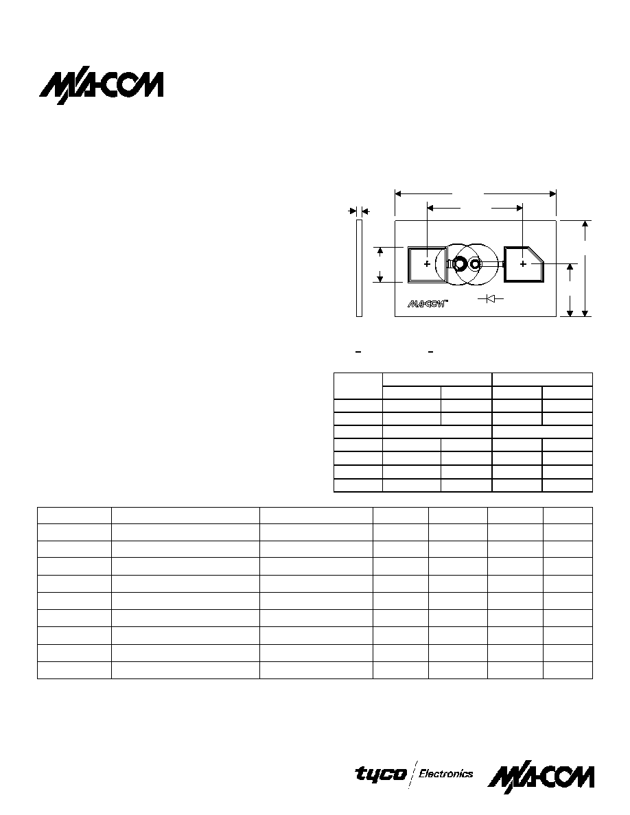
Case Style
ODS-1264
1, 2, 3
1.
Dimensions are in inches, () are in mm.
2.
Unless otherwise noted, tolerance are inches
+ .001” (millimeters + .025 mm).
3.
Schematic is for junction side up.
INCHES
MILLIMETERS
DIM.
MIN.
MAX.
MIN.
MAX.
A
0.0082
0.0092
0.209
0.233
B
0.0141
0.0151
0.359
0.383
C
0.0035 Typ.
D
.00038
0.0048
0.097
0.121
E
0.0085
0.0095
0.217
0.240
F
0.0023
0.0033
0.059
0.083
G
0.0048
0.0058
0.123
0.147
0.090 Typ.
MA4FCP200
Silicon Flip Chip
PIN Diode
G
C
B
E
A
D
Electrical Specifications @ +25°C
Symbol
Parameter
Test Conditions
Units
Min.
Typ.
Max.
CT
Total Capacitance
-10 Volts, 1 MHz
1
pF
0.020
0.030
CT
Total Capacitance
-10 Volts, 1 GHz
1, 3
pF
0.015
RS
Series Resistance
50 mA, 100 MHz
2, 3
2.4
RS
Series Resistance
50 mA, 1 GHz
2, 3
2.8
VF
Forward Voltage
100 mA
V
1.25
1.50
VR
Reverse Voltage
10
A
V
-70
-100
IR
Reverse Current
-70 V
A
10
RθJL
Thermal Resistance
°C/W
< 860
TL
Lifetime
10 mA / 6 mA
ns
100
1. Total capacitance is equivalent to the sum of junction capacitance Cj and parasitic capacitance.
2. Series resistance RS is equivalent to the total diode series resistance including the junction resistance Rj.
3. RS and CP measures on an HP4291A with die mounted in an ODS-186 package with conductive silver epoxy.
4. Steady-state RθJL measured with die mounted in an ODS-186 package with conductive silver epoxy.
1
相关PDF资料 |
PDF描述 |
|---|---|
| MA4FCS100M-1283T | SILICON, MEDIUM BARRIER SCHOTTKY, KU BAND, MIXER DIODE |
| MA4GP030-1056 | GALLIUM ARSENIDE, PIN DIODE |
| MA4GP030-277 | GALLIUM ARSENIDE, PIN DIODE |
| MA4GP022-137 | GALLIUM ARSENIDE, PIN DIODE |
| MA4L021-1056 | SILICON, PIN DIODE |
相关代理商/技术参数 |
参数描述 |
|---|---|
| MA4FCP200-W | 制造商:MA-COM 制造商全称:M/A-COM Technology Solutions, Inc. 功能描述:Flip Chip PIN Diode |
| MA4FCP300 | 制造商:M/A-COM Technology Solutions 功能描述:HMIC FLIP CHIP PIN - Gel-pak, waffle pack, wafer, diced wafer on film 制造商:M/A-COM Technology Solutions 功能描述:RF PIN DIODE |
| MA4FCP300-T | 制造商:MA-COM 制造商全称:M/A-COM Technology Solutions, Inc. 功能描述:Silicon Flip Chip PIN Diode |
| MA4FCP300-W | 制造商:MA-COM 制造商全称:M/A-COM Technology Solutions, Inc. 功能描述:Silicon Flip Chip PIN Diode |
| MA4FCP305 | 制造商:M/A-COM Technology Solutions 功能描述:Diode PIN Switch 40V 2-Pin Waffle |
发布紧急采购,3分钟左右您将得到回复。