- 您现在的位置:买卖IC网 > PDF目录385520 > MAX1031BETI-T (MAXIM INTEGRATED PRODUCTS INC) 10-Bit 300ksps ADCs with FIFO, Temp Sensor, Internal Reference PDF资料下载
参数资料
| 型号: | MAX1031BETI-T |
| 厂商: | MAXIM INTEGRATED PRODUCTS INC |
| 元件分类: | ADC |
| 英文描述: | 10-Bit 300ksps ADCs with FIFO, Temp Sensor, Internal Reference |
| 中文描述: | 16-CH 10-BIT SUCCESSIVE APPROXIMATION ADC, SERIAL ACCESS, QCC28 |
| 封装: | 5 X 5 MM, TQFN-28 |
| 文件页数: | 15/23页 |
| 文件大小: | 254K |
| 代理商: | MAX1031BETI-T |
M
10-Bit 300ksps ADCs with FIFO,
Temp Sensor, Internal Reference
______________________________________________________________________________________
15
set to 1. Select scan mode 10 to scan the same channel
multiple times. Clock mode 11 disables averaging.
Reset Register
Write to the reset register (as shown in Table 7) to clear
the FIFO or to reset all registers to their default states.
Set the
RESET
bit to 1 to reset the FIFO. Set the reset
bit to zero to return the MAX1027/MAX1029/MAX1031
to its default power-up state.
Power-Up Default State
The MAX1027/MAX1029/MAX1031 power up with all
blocks in shutdown, including the reference. All registers
power up in state 00000000, except for the setup regis-
ter, which powers up in clock mode 10 (CKSEL1 = 1).
Temperature Measurements
The MAX1027/MAX1029/MAX1031 perform tempera-
ture measurements with an internal diode-connected
transistor. The diode bias current changes from 68μA
to 4μA to produce a temperature-dependent bias volt-
age difference. The second conversion result at 4μA is
subtracted from the first at 68μA to calculate a digital
value that is proportional to absolute temperature. The
output data appearing at DOUT is the above digital
code minus an offset to adjust from Kelvin to Celsius.
The reference voltage used for the temperature mea-
surements is derived from the internal reference source
to ensure a resolution of 1/8 of a degree.
Output Data Format
Figures 4–7 illustrate the conversion timing for the
MAX1027/MAX1029/MAX1031. The 10-bit conversion
result is output in MSB-first format with four leading
zeroes and two trailing sub-bits. The 12-bit temperature
measurement is output with four leading zeros. DIN
data is latched into the serial interface on the rising
edge of SCLK. Data on DOUT transitions on the falling
edge of SCLK. Conversions in clock modes 00 and 01
are initiated by
CNVST
. Conversions in clock modes 10
and 11 are initiated by writing an input data byte to the
conversion register. Data is binary for unipolar mode and
two’s complement for bipolar mode.
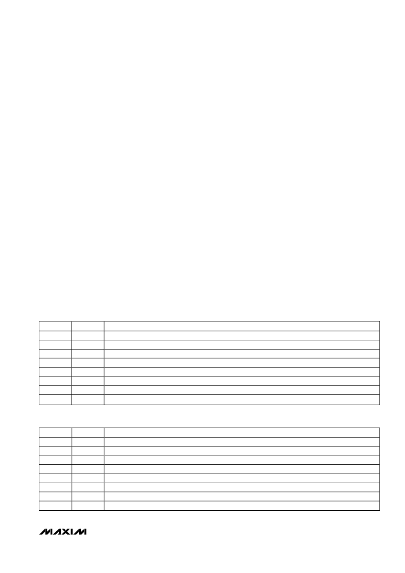
BIT NAME
UCH0/1
UCH2/3
UCH4/5
UCH6/7
UCH8/9
UCH10/11
UCH12/13
UCH14/15
BIT
FUNCTION
7 (MSB)
6
5
4
3
2
1
0 (LSB)
Set to 1 to configure AIN0 and AIN1 for unipolar differential conversion.
Set to 1 to configure AIN2 and AIN3 for unipolar differential conversion.
Set to 1 to configure AIN4 and AIN5 for unipolar differential conversion.
Set to 1 to configure AIN6 and AIN7 for unipolar differential conversion.
Set to 1 to configure AIN8 and AIN9 for unipolar differential conversion (MAX1029/MAX1031 only).
Set to 1 to configure AIN10 and AIN11 for unipolar differential conversion (MAX1029/MAX1031 only).
Set to 1 to configure AIN12 and AIN13 for unipolar differential conversion (MAX1031 only).
Set to 1 to configure AIN14 and AIN15 for unipolar differential conversion (MAX1031 only).
Table 4. Unipolar Mode Register (Addressed Through Setup Register)
BIT NAME
BCH0/1
BCH2/3
BCH4/5
BCH6/7
BCH8/9
BCH10/11
BCH12/13
BCH14/15
BIT
FUNCTION
7 (MSB)
6
5
4
3
2
1
0 (LSB)
Set to 1 to configure AIN0 and AIN1 for bipolar differential conversion.
Set to 1 to configure AIN2 and AIN3 for bipolar differential conversion.
Set to 1 to configure AIN4 and AIN5 for bipolar differential conversion.
Set to 1 to configure AIN6 and AIN7 for bipolar differential conversion.
Set to 1 to configure AIN8 and AIN9 for bipolar differential conversion (MAX1029/MAX1031 only).
Set to 1 to configure AIN10 and AIN11 for bipolar differential conversion (MAX1029/MAX1031 only).
Set to 1 to configure AIN12 and AIN13 for bipolar differential conversion (MAX1031 only).
Set to 1 to configure AIN14 and AIN15 for bipolar differential conversion (MAX1031 only).
Table 5. Bipolar Mode Register (Addressed Through Setup Register)
相关PDF资料 |
PDF描述 |
|---|---|
| MAX104 | 【5V, 1Gsps, 8-Bit ADC with On-Chip 2.2GHz Track/Hold Amplifier |
| MAX104CHC | 【5V, 1Gsps, 8-Bit ADC with On-Chip 2.2GHz Track/Hold Amplifier |
| MAX105 | Dual, 6-Bit, 800Msps ADC with On-Chip, Wideband Input Amplifier |
| MAX105ECS | Dual, 6-Bit, 800Msps ADC with On-Chip, Wideband Input Amplifier |
| MAX1067ACEE | Multichannel, 14-Bit, 200ksps Analog-to-Digital Converters |
相关代理商/技术参数 |
参数描述 |
|---|---|
| MAX1032 | 制造商:MAXIM 制造商全称:Maxim Integrated Products 功能描述:8-/4-Channel, 【12V Multirange Inputs, Serial 14-Bit ADCs |
| MAX1032_11 | 制造商:MAXIM 制造商全称:Maxim Integrated Products 功能描述:8- and 4-Channel, ±3 x VREF Multirange Inputs, Serial 14-Bit ADCs |
| MAX1032_1112 | 制造商:MAXIM 制造商全称:Maxim Integrated Products 功能描述:8- and 4-Channel, 3 x VREF Multirange Inputs, Serial 14-Bit ADCs |
| MAX1032BEUG+ | 功能描述:模数转换器 - ADC 14Bit 8Ch 12V Serial ADC RoHS:否 制造商:Texas Instruments 通道数量:2 结构:Sigma-Delta 转换速率:125 SPs to 8 KSPs 分辨率:24 bit 输入类型:Differential 信噪比:107 dB 接口类型:SPI 工作电源电压:1.7 V to 3.6 V, 2.7 V to 5.25 V 最大工作温度:+ 85 C 安装风格:SMD/SMT 封装 / 箱体:VQFN-32 |
| MAX1032BEUG+T | 功能描述:模数转换器 - ADC 14Bit 8Ch 12V Serial ADC RoHS:否 制造商:Texas Instruments 通道数量:2 结构:Sigma-Delta 转换速率:125 SPs to 8 KSPs 分辨率:24 bit 输入类型:Differential 信噪比:107 dB 接口类型:SPI 工作电源电压:1.7 V to 3.6 V, 2.7 V to 5.25 V 最大工作温度:+ 85 C 安装风格:SMD/SMT 封装 / 箱体:VQFN-32 |
发布紧急采购,3分钟左右您将得到回复。