- 您现在的位置:买卖IC网 > PDF目录9894 > MAX1065BCUI+ (Maxim Integrated Products)IC ADC 14BIT 165KSPS 28TSSOP PDF资料下载
参数资料
| 型号: | MAX1065BCUI+ |
| 厂商: | Maxim Integrated Products |
| 文件页数: | 13/14页 |
| 文件大小: | 0K |
| 描述: | IC ADC 14BIT 165KSPS 28TSSOP |
| 产品培训模块: | Lead (SnPb) Finish for COTS Obsolescence Mitigation Program |
| 标准包装: | 50 |
| 位数: | 14 |
| 采样率(每秒): | 165k |
| 数据接口: | 并联 |
| 转换器数目: | 1 |
| 功率耗散(最大): | 16mW |
| 电压电源: | 单电源 |
| 工作温度: | 0°C ~ 70°C |
| 安装类型: | 表面贴装 |
| 封装/外壳: | 28-TSSOP(0.173",4.40mm 宽) |
| 供应商设备封装: | 28-TSSOP |
| 包装: | 管件 |
| 输入数目和类型: | 1 个单端,单极 |
MAX1065/MAX1066
Detailed Description
Converter Operation
The MAX1065/MAX1066 use a successive-approximation
(SAR) conversion technique with an inherent track-and-
hold (T/H) stage to convert an analog input into a 14-bit
digital output. Parallel outputs provide a high-speed inter-
face to most microprocessors (Ps). The
Functional
Diagram shows a simplified internal architecture of the
MAX1065/MAX1066. Figure 3 shows a typical application
circuit for the MAX1066.
Analog Input
The equivalent input circuit is shown in Figure 4. A
switched capacitor digital-to-analog converter (DAC)
provides an inherent track-and-hold function. The sin-
gle-ended input is connected between AIN and AGND.
Input Bandwidth
The ADC’s input-tracking circuitry has a 4MHz small-
signal bandwidth, so it is possible to digitize high-
speed transient events and measure periodic signals
with bandwidths exceeding the ADC’s sampling rate by
using undersampling techniques. To avoid aliasing of
unwanted high-frequency signals into the frequency
band of interest, use antialias filtering.
Internal protection diodes, which clamp the analog
input to AVDD and/or AGND, allow the input to swing
from AGND - 0.3V to AVDD + 0.3V, without damaging
the device.
If the analog input exceeds 300mV beyond the sup-
plies, limit the input current to 10mA.
Track and Hold (T/H)
In track mode, the analog signal is acquired on the
internal hold capacitor. In hold mode, the T/H switches
open and the capacitive DAC samples the analog input.
Low-Power, 14-Bit Analog-to-Digital Converters
with Parallel Interface
8
_______________________________________________________________________________________
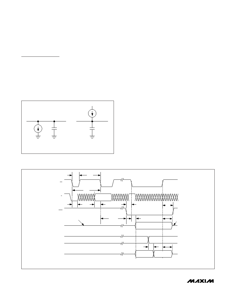
CS
R/C
REF POWER-
DOWN BIT
EOC
D0–D13
HBEN*
DATA VALID
D7/D13–D0/D8*
HIGH/LOW
BYTE VALID
tACQ
tCONV
tCSH
tCSL
tDH
tDO
tDO1
tEOC
*HBEN AND BYTE-WIDE DATA BUS AVAILABLE ON MAX1066 ONLY.
tDS
tDV
HI–Z
HI-Z
HIGH/LOW
BYTE VALID
tBR
Figure 2. MAX1065/MAX1066 Timing Diagram
DGND
1mA
CLOAD = 20pF
D0–D13
CLOAD = 20pF
1mA
DGND
DVDD
a) HIGH-Z TO VOH,
VOL TO VOH, AND
VOH TO HIGH-Z
b) HIGH-Z TO VOL,
VOH TO VOL, AND
VOL TO HIGH-Z
Figure 1. Load Circuits for D0–D13 Enable Time, CS to D0–D13
Delay Time and Bus Relinquish Time
相关PDF资料 |
PDF描述 |
|---|---|
| VE-2WD-MX-F2 | CONVERTER MOD DC/DC 85V 75W |
| MAX1003CAX+ | IC ADC 6BIT 90MSPS DL 36-SSOP |
| MAX1497EAI+ | IC ADC 3 1/2DIG W/LED DVR 28-SSO |
| MS3122E22-21S | CONN RCPT 21POS BOX MOUNT W/SCKT |
| MAX1497EPI+ | IC ADC 3 1/2DIG W/LED DVR 28-DIP |
相关代理商/技术参数 |
参数描述 |
|---|---|
| MAX1065BCUI+ | 功能描述:模数转换器 - ADC Low-Power 14-Bit w/Parallel Interface RoHS:否 制造商:Texas Instruments 通道数量:2 结构:Sigma-Delta 转换速率:125 SPs to 8 KSPs 分辨率:24 bit 输入类型:Differential 信噪比:107 dB 接口类型:SPI 工作电源电压:1.7 V to 3.6 V, 2.7 V to 5.25 V 最大工作温度:+ 85 C 安装风格:SMD/SMT 封装 / 箱体:VQFN-32 |
| MAX1065BCUI+T | 功能描述:模数转换器 - ADC Low-Power 14-Bit w/Parallel Interface RoHS:否 制造商:Texas Instruments 通道数量:2 结构:Sigma-Delta 转换速率:125 SPs to 8 KSPs 分辨率:24 bit 输入类型:Differential 信噪比:107 dB 接口类型:SPI 工作电源电压:1.7 V to 3.6 V, 2.7 V to 5.25 V 最大工作温度:+ 85 C 安装风格:SMD/SMT 封装 / 箱体:VQFN-32 |
| MAX1065BCUI-T | 功能描述:模数转换器 - ADC RoHS:否 制造商:Texas Instruments 通道数量:2 结构:Sigma-Delta 转换速率:125 SPs to 8 KSPs 分辨率:24 bit 输入类型:Differential 信噪比:107 dB 接口类型:SPI 工作电源电压:1.7 V to 3.6 V, 2.7 V to 5.25 V 最大工作温度:+ 85 C 安装风格:SMD/SMT 封装 / 箱体:VQFN-32 |
| MAX1065BEUI | 功能描述:模数转换器 - ADC RoHS:否 制造商:Texas Instruments 通道数量:2 结构:Sigma-Delta 转换速率:125 SPs to 8 KSPs 分辨率:24 bit 输入类型:Differential 信噪比:107 dB 接口类型:SPI 工作电源电压:1.7 V to 3.6 V, 2.7 V to 5.25 V 最大工作温度:+ 85 C 安装风格:SMD/SMT 封装 / 箱体:VQFN-32 |
| MAX1065BEUI+ | 功能描述:模数转换器 - ADC Low-Power 14-Bit w/Parallel Interface RoHS:否 制造商:Texas Instruments 通道数量:2 结构:Sigma-Delta 转换速率:125 SPs to 8 KSPs 分辨率:24 bit 输入类型:Differential 信噪比:107 dB 接口类型:SPI 工作电源电压:1.7 V to 3.6 V, 2.7 V to 5.25 V 最大工作温度:+ 85 C 安装风格:SMD/SMT 封装 / 箱体:VQFN-32 |
发布紧急采购,3分钟左右您将得到回复。